
附件12: 《模拟集成电路分析与设计》教学大纲 课程编号:0208096202 课程名称:模拟集成电路分析与设计 学时数:50 学分:2.5 开课时间:秋季 开课学院:电子科学与工程学院 授课对像:硕士/博士 先修课程:半导体器件、半导体工艺、模拟电路基础 一、教学目的 模拟集成电路是集成电路的重要组成部分。通过本课程教学,使学生掌握集成电路中有 源器件的结构、特性、大小信号模型,掌握模拟集成电路中的基本放大器的结构与性能,掌 握重要放大器的结构、稳定性分析方法,了解放大器的系统设计方法,掌握全差分放大器、 多级运算放大器、电流输入运算放大器、轨对轨放大器以及四种反馈放大器的结构与基本设 计方法,具备较强的模拟集成电路分析与设计能力。 二、教学内容与要求 第一章集成电路有源器件的模型与比较(4学时) 1本章教学内容: 51.1PN结(1学时) §1.2双极型晶体管的大、小信号模型(1学时) 51.3金属场效应管的大、小信号模型(1.5学时) 51.4BT与M0S器件的对比(0.5学时) 2本章教学要求:通过本章课程学习,要求学生掌握模拟集成电路中无源器件的重要特 性、大小信号模型,理解器件参数对电路性能的影响。 3本章教学重点:集成电路中PN结、BT、CMOS有源器件的大小信号模型以及如何利 用这些模型分析集成电路的特性。 4本章教学难点:根据有源器件的重要参数的大小来判断其性能,并由此确定电路设计 方案。 第二章放大器、源极跟随器与共源共栅放大器(4学时) 1本章教学内容: 52.1单管放大级(1学时) 52.2源跟随器(1学时) 52.3共源共栅放大器(2学时) 2本章教学要求:通过本章课程学习,要求学生掌握模拟集成电路中三种基本放大电路 的结构与特性。 3本章教学重点:(1)基于三种基本单管放大器的大/小信号模型求解增益、带宽、增 益带宽:(2)增益、带宽、增益带宽对电路性能的影响。 4本章教学难点:(1)AB放大特性:(2)衬偏效应对源随器的容性、阻性、感性特性 的影响:(3)折叠共源共栅的输出阻抗和增益求解方法。 ·14
·1· 附件 12: 《模拟集成电路分析与设计》教学大纲 课程编号:0208096202 课程名称:模拟集成电路分析与设计 学时数:50 学分:2.5 开课时间:秋季 开课学院:电子科学与工程学院 授课对象:硕士/博士 先修课程:半导体器件、半导体工艺、模拟电路基础 一、教学目的 模拟集成电路是集成电路的重要组成部分。通过本课程教学,使学生掌握集成电路中有 源器件的结构、特性、大小信号模型,掌握模拟集成电路中的基本放大器的结构与性能,掌 握重要放大器的结构、稳定性分析方法,了解放大器的系统设计方法,掌握全差分放大器、 多级运算放大器、电流输入运算放大器、轨对轨放大器以及四种反馈放大器的结构与基本设 计方法,具备较强的模拟集成电路分析与设计能力。 二、教学内容与要求 第一章 集成电路有源器件的模型与比较(4 学时) 1 本章教学内容: §1.1 PN 结 (1 学时) §1.2 双极型晶体管的大、小信号模型 (1 学时) §1.3 金属场效应管的大、小信号模型 (1.5 学时) §1.4 BJT 与 MOS 器件的对比(0.5 学时) 2 本章教学要求:通过本章课程学习,要求学生掌握模拟集成电路中无源器件的重要特 性、大小信号模型,理解器件参数对电路性能的影响。 3 本章教学重点:集成电路中 PN 结、BJT、CMOS 有源器件的大小信号模型以及如何利 用这些模型分析集成电路的特性。 4 本章教学难点:根据有源器件的重要参数的大小来判断其性能,并由此确定电路设计 方案。 第二章 放大器、源极跟随器与共源共栅放大器(4 学时) 1 本章教学内容: §2.1 单管放大级 (1 学时) §2.2 源跟随器 (1 学时) §2.3 共源共栅放大器(2 学时) 2 本章教学要求:通过本章课程学习,要求学生掌握模拟集成电路中三种基本放大电路 的结构与特性。 3 本章教学重点:(1)基于三种基本单管放大器的大/小信号模型求解增益、带宽、增 益带宽;(2)增益、带宽、增益带宽对电路性能的影响。 4 本章教学难点:(1)AB 放大特性;(2)衬偏效应对源随器的容性、阻性、感性特性 的影响;(3)折叠共源共栅的输出阻抗和增益求解方法

第三章差分电压与电流放大器(5学时) 1本章教学内容: 3.1电流镜(1.5学时) §3.2差分对(2学时) 3.3电压、电流差分放大器(1.5学时) 2本章教学要求:通过本章课程学习,要求学生掌握模拟集成电路中具有对称结构的电 流镜和差分对的结构,掌握基本电流镜和改进电流镜结构及特性, 掌握电压差分放大器的直流和交流特性、以及OTA的直流和交流特 性。 3本章教学重点:(1)电流镜的匹配性:(2)差分对跨道的求解:(3)电压、电流差 分放大器的差异。 4本章教学难点:(1)如何提升电流镜的匹配性:(2)如何改善差分对的阻抗特性和增 益特性。 第四章基本晶体管级的噪声性能(4学时) 1本章教学内容: 54.1噪声的定义(1学时) 54.2运放的噪声(0.5学时) 54.3跟随器的噪声(0.5学时) 54.4共源共栅的噪声(0.5学时) §4.5电流镜的噪声(0.5学时) 54.6差分对的噪声(0.5学时) 54.7容性噪声匹配(0.5学时) 2本章教学要求:通过本章课程学习,要求学生了解噪声的基本定义、几种简单放大器 的噪声及基本晶体管级噪声的性能和容性噪声匹配 3本章教学重点:几种简单放大器的噪声模型。 4本章教学难点:基本晶体管级噪声的性能和容性噪声匹配。 第五章运算放大器的稳定性(4学时) 1本章教学内容: 55.1运算放大器的应用(2学时) 55.2两级运放的稳定性(0.5学时) 55.3极点分裂(0.5学时) 5.4正零点补偿(0.5学时) 55.5三级运放的稳定性(0.5学时) 2本章教学要求:通过本章课程学习,要求学生掌握运算放大器稳定性概念和两级和三 级运放的稳定性分析方法,掌握包括极点分裂和右半平面零点补偿 在内的运算放大器稳定性补偿方法。 3本章教学重点:(1)运放的稳定性分析方法:(2)运算放大器米勒补偿方法。 4本章教学难点:(1)GBW对运放稳定性的影响:(2)各种米勒补偿方法及补偿效果 分析。 第六章运算放大器的系统性设计(4学时) ·2
·2· 第三章 差分电压与电流放大器(5 学时) 1 本章教学内容: §3.1 电流镜(1.5 学时) §3.2 差分对(2 学时) §3.3 电压、电流差分放大器 (1.5 学时) 2 本章教学要求:通过本章课程学习,要求学生掌握模拟集成电路中具有对称结构的电 流镜和差分对的结构,掌握基本电流镜和改进电流镜结构及特性, 掌握电压差分放大器的直流和交流特性、以及 OTA 的直流和交流特 性。 3 本章教学重点:(1)电流镜的匹配性;(2)差分对跨道的求解;(3)电压、电流差 分放大器的差异。 4 本章教学难点:(1)如何提升电流镜的匹配性;(2)如何改善差分对的阻抗特性和增 益特性。 第四章 基本晶体管级的噪声性能(4 学时) 1 本章教学内容: §4.1 噪声的定义 (1 学时) §4.2 运放的噪声 (0.5 学时) §4.3 跟随器的噪声 (0.5 学时) §4.4 共源共栅的噪声 (0.5 学时) §4.5 电流镜的噪声 (0.5 学时) §4.6 差分对的噪声 (0.5 学时) §4.7 容性噪声匹配 (0.5 学时) 2 本章教学要求:通过本章课程学习,要求学生了解噪声的基本定义、几种简单放大器 的噪声及基本晶体管级噪声的性能和容性噪声匹配 3 本章教学重点:几种简单放大器的噪声模型。 4 本章教学难点:基本晶体管级噪声的性能和容性噪声匹配。 第五章 运算放大器的稳定性(4 学时) 1 本章教学内容: §5.1 运算放大器的应用(2 学时) §5.2 两级运放的稳定性(0.5 学时) §5.3 极点分裂(0.5 学时) §5.4 正零点补偿(0.5 学时) §5.5 三级运放的稳定性(0.5 学时) 2 本章教学要求:通过本章课程学习,要求学生掌握运算放大器稳定性概念和两级和三 级运放的稳定性分析方法,掌握包括极点分裂和右半平面零点补偿 在内的运算放大器稳定性补偿方法。 3 本章教学重点:(1)运放的稳定性分析方法;(2)运算放大器米勒补偿方法。 4 本章教学难点:(1)GBW 对运放稳定性的影响;(2)各种米勒补偿方法及补偿效果 分析。 第六章 运算放大器的系统性设计(4 学时)
1本章教学内容: 56.1单级OTA设计(1学时) 56.2米勒CMOS OTA设计(0.5学时) 6.3GBW和相位裕度设计(1学时) 56.4输入范围、输出范围、SR设计(1.5学时) 2本章教学要求:通过本章课程学习,要求学生掌握单级和两级米勒OTA的设计方法 与电路特性,掌握运放的输入、输出范围、S、相位裕度等概念。 3本章教学重点:(1)OTA电路的基本设计方法:(2)OTA电路的补偿;(3)OTA电路 的关键参数的定义、设计。 4本章教学难点:(1)米勒OTA的设计:(2)OTA运放的输入范围、输出范围、SR、相 位裕度等参数的折中考虑。 第七章重要的运算放大器结构(4学时) 1本章教学内容: 57.1简单CMOS0TA(0.5学时) §7.2米勒CMOS OTA(0.5学时) §7.3对称CMOS OTA(1学时) §7.4折叠共源共栅OTA(1学时) 57.5其他运放(1学时) 2本章教学要求:通过本章课程学习,要求学生掌握几种重要运算放大器的结构、特性。 3本章教学重点:(1)米勒OTA的结构和工作原理、特性:(2)对称CMOS OTA的结构 和工作原理、特性:(3)折叠共源共栅OTA的结构和工作原理、特 性。 4本章教学难点:多级OTA的GBW分析。 第八章全差分放大器(4学时) 1本章教学内容: §8.1设计要求(0.5学时) 58.2具有线性MOS的全差分运放(0.5学时) 58.3带误差放大器和源随器的全差分运放(0.5学时) 58.4带源随器的折叠共源共栅OTA(0.5学时) 58.5其他全差分运放(1学时) §8.6全差分放大器设计练习(1学时) 2本章教学要求:通过本章课程学习,要求学生掌握全差分放大器及改进结构全差分放 大器的结构、工作原理与特性。 3本章教学重点:(1)全差分放大器的结构和工作原理:(2)CMB的结构与作用:(3) 改进全差分放大器的结构、工作原理与性能分析。 4本章教学难点:(1)差模和共模负反馈的结构与特性差异:(2)CMFB电路的设计与 分析。 第九章多级运算放大器的设计(4学时) 1本章教学内容: 59.1设计过程(1.5学时) 59.2嵌套式米勒设计(1.5学时) ·3·
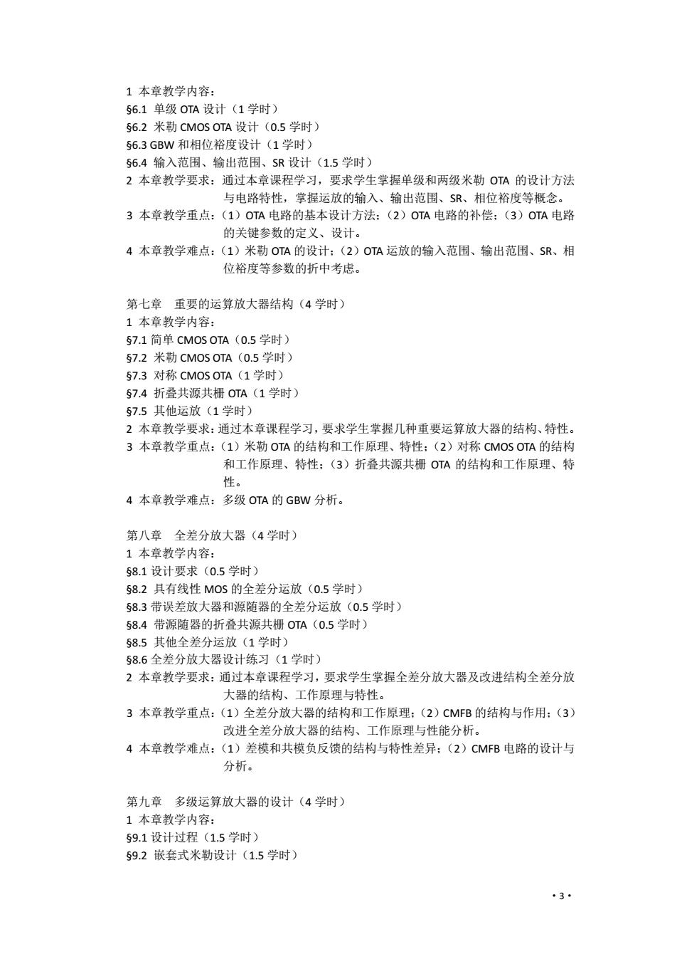
·3· 1 本章教学内容: §6.1 单级 OTA 设计(1 学时) §6.2 米勒 CMOS OTA 设计(0.5 学时) §6.3 GBW 和相位裕度设计(1 学时) §6.4 输入范围、输出范围、SR 设计(1.5 学时) 2 本章教学要求:通过本章课程学习,要求学生掌握单级和两级米勒 OTA 的设计方法 与电路特性,掌握运放的输入、输出范围、SR、相位裕度等概念。 3 本章教学重点:(1)OTA 电路的基本设计方法;(2)OTA 电路的补偿;(3)OTA 电路 的关键参数的定义、设计。 4 本章教学难点:(1)米勒 OTA 的设计;(2)OTA 运放的输入范围、输出范围、SR、相 位裕度等参数的折中考虑。 第七章 重要的运算放大器结构(4 学时) 1 本章教学内容: §7.1 简单 CMOS OTA(0.5 学时) §7.2 米勒 CMOS OTA(0.5 学时) §7.3 对称 CMOS OTA(1 学时) §7.4 折叠共源共栅 OTA(1 学时) §7.5 其他运放(1 学时) 2 本章教学要求:通过本章课程学习,要求学生掌握几种重要运算放大器的结构、特性。 3 本章教学重点:(1)米勒 OTA 的结构和工作原理、特性;(2)对称 CMOS OTA 的结构 和工作原理、特性;(3)折叠共源共栅 OTA 的结构和工作原理、特 性。 4 本章教学难点:多级 OTA 的 GBW 分析。 第八章 全差分放大器(4 学时) 1 本章教学内容: §8.1 设计要求(0.5 学时) §8.2 具有线性 MOS 的全差分运放(0.5 学时) §8.3 带误差放大器和源随器的全差分运放(0.5 学时) §8.4 带源随器的折叠共源共栅 OTA(0.5 学时) §8.5 其他全差分运放(1 学时) §8.6 全差分放大器设计练习(1 学时) 2 本章教学要求:通过本章课程学习,要求学生掌握全差分放大器及改进结构全差分放 大器的结构、工作原理与特性。 3 本章教学重点:(1)全差分放大器的结构和工作原理;(2)CMFB 的结构与作用;(3) 改进全差分放大器的结构、工作原理与性能分析。 4 本章教学难点:(1)差模和共模负反馈的结构与特性差异;(2)CMFB 电路的设计与 分析。 第九章 多级运算放大器的设计(4 学时) 1 本章教学内容: §9.1 设计过程(1.5 学时) §9.2 嵌套式米勒设计(1.5 学时)
59.3低功耗设计(0.5学时) 59.4对比(0.5学时) 2本章教学要求:通过本章课程学习,要求学生了解三级放大器的稳定性原理以及减少 电路功耗的方法,掌握多级放大器的频率补偿方法。 3本章教学重点:(1)放大电路的设计流程:(2)嵌套式米勒电路的分析与设计:(3) 电路低功耗设计思想。 4本章教学难点:(1)嵌套式米勒电路的分析与设计:(3)低功耗电路分析。 第十章轨对轨输入与输出放大器(4学时) 1本章教学内容: §10.1为什么轨对轨(0.5学时) 510.23倍电流镜轨对轨放大器(1学时) §10.3齐纳二极管轨对轨放大器(0.5学时) 510.41.5V电流调节轨对轨放大器(1学时) 510.51.3V电源调节轨对轨放大器(0.5学时) §10.6其他轨对轨放大器(0.5学时) 2本章教学要求:通过本章课程学习,要求学生了解为什么要轨对轨,掌握3倍电流镜、 齐纳二极管轨对轨放大器原理,了解电流调节、电源调节等轨对轨 放大器的基本结构和工作原理。 3本章教学重点:(1)3倍电流镜轨对轨放大器结构与原理:(2)差分对跨道的求解: (3)电压、电流差分放大器的差异。 4本章教学难点:(1)如何提升电流镜的匹配性:(2)如何改善差分对的阻抗特性和增 益特性。 轨对轨放大器是一种特殊放大器,要求同学们了解为什么要轨对轨,掌握3倍电流镜、 齐纳二极管轨对轨放大器原理,了解电流、电源调节等轨对轨放大器的基本结构和工作原理。 第十一章反馈放大器(6学时) 1本章教学内容: §11.1反馈定义(1学时) 511.2串并电压反馈放大器(1.5学时) 511.3串串跨导反馈放大器(1.5学时) §11.4并并跨阻反馈放大器(1学时) §11.5并串电流反馈放大器(1学时) 2本章教学要求:通过本章课程学习,要求学生掌握开环增益、闭环增益等的定义,掌 握四种反馈类型的电路基本结构、开/闭环增益和输入/输出电阻的分 析方法和分析结果。 3本章教学重点:四种反馈类型的电路基本结构、开/闭环增益和输入/输出电阻的分析 方法。 4本章教学难点:(1)负反馈电路类型的判断:(2)负反馈放大器的设计方法。 第十二章带隙与电流基准电路(3学时) 1本章教学内容: 512.1双极性带隙基准(1学时) ·4·
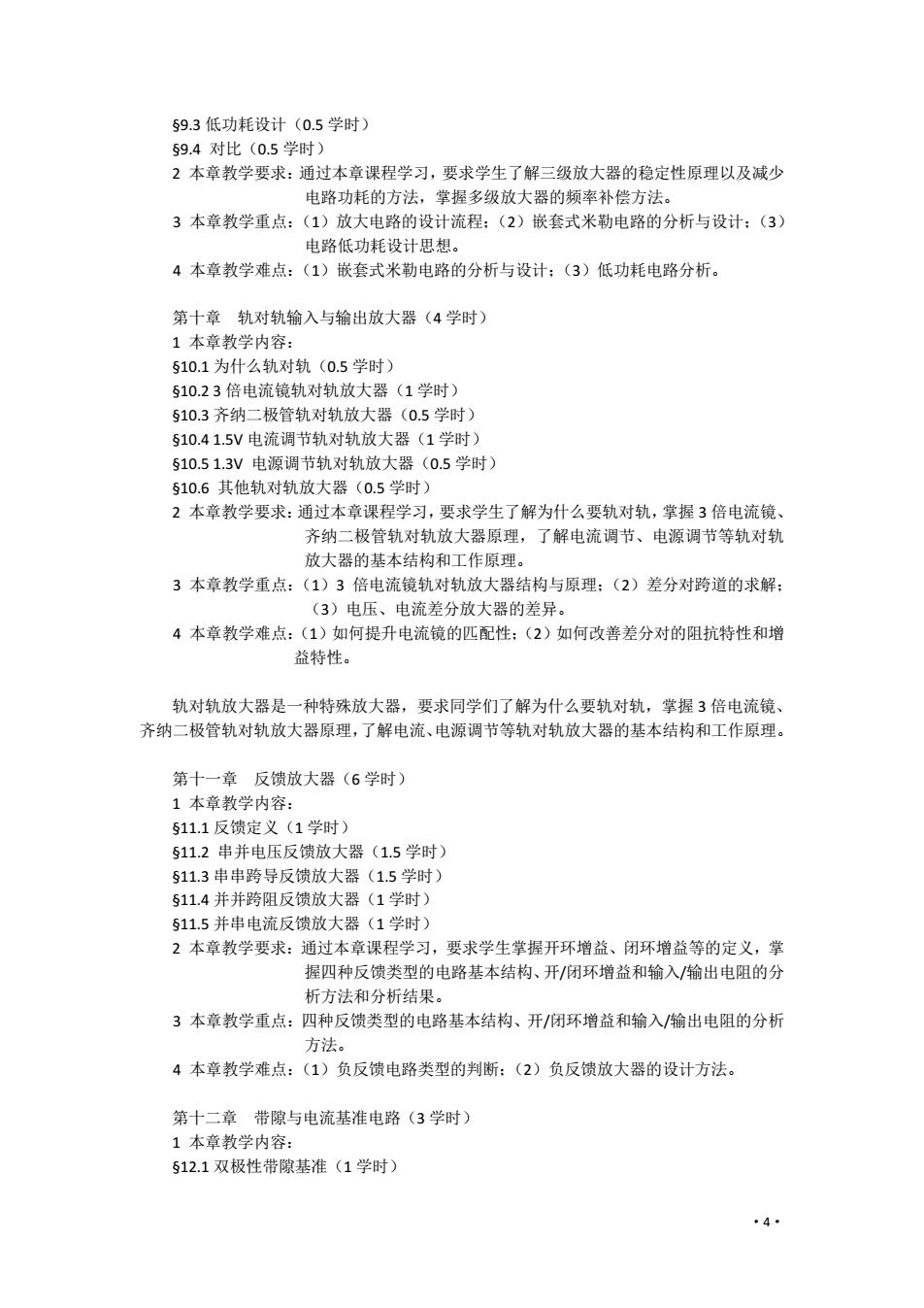
·4· §9.3 低功耗设计(0.5 学时) §9.4 对比(0.5 学时) 2 本章教学要求:通过本章课程学习,要求学生了解三级放大器的稳定性原理以及减少 电路功耗的方法,掌握多级放大器的频率补偿方法。 3 本章教学重点:(1)放大电路的设计流程;(2)嵌套式米勒电路的分析与设计;(3) 电路低功耗设计思想。 4 本章教学难点:(1)嵌套式米勒电路的分析与设计;(3)低功耗电路分析。 第十章 轨对轨输入与输出放大器(4 学时) 1 本章教学内容: §10.1 为什么轨对轨(0.5 学时) §10.2 3 倍电流镜轨对轨放大器(1 学时) §10.3 齐纳二极管轨对轨放大器(0.5 学时) §10.4 1.5V 电流调节轨对轨放大器(1 学时) §10.5 1.3V 电源调节轨对轨放大器(0.5 学时) §10.6 其他轨对轨放大器(0.5 学时) 2 本章教学要求:通过本章课程学习,要求学生了解为什么要轨对轨,掌握 3 倍电流镜、 齐纳二极管轨对轨放大器原理,了解电流调节、电源调节等轨对轨 放大器的基本结构和工作原理。 3 本章教学重点:(1)3 倍电流镜轨对轨放大器结构与原理;(2)差分对跨道的求解; (3)电压、电流差分放大器的差异。 4 本章教学难点:(1)如何提升电流镜的匹配性;(2)如何改善差分对的阻抗特性和增 益特性。 轨对轨放大器是一种特殊放大器,要求同学们了解为什么要轨对轨,掌握 3 倍电流镜、 齐纳二极管轨对轨放大器原理,了解电流、电源调节等轨对轨放大器的基本结构和工作原理。 第十一章 反馈放大器(6 学时) 1 本章教学内容: §11.1 反馈定义(1 学时) §11.2 串并电压反馈放大器(1.5 学时) §11.3 串串跨导反馈放大器(1.5 学时) §11.4 并并跨阻反馈放大器(1 学时) §11.5 并串电流反馈放大器(1 学时) 2 本章教学要求:通过本章课程学习,要求学生掌握开环增益、闭环增益等的定义,掌 握四种反馈类型的电路基本结构、开/闭环增益和输入/输出电阻的分 析方法和分析结果。 3 本章教学重点:四种反馈类型的电路基本结构、开/闭环增益和输入/输出电阻的分析 方法。 4 本章教学难点:(1)负反馈电路类型的判断;(2)负反馈放大器的设计方法。 第十二章 带隙与电流基准电路(3 学时) 1 本章教学内容: §12.1 双极性带隙基准(1 学时)
§12.2CM0S带隙基准(0.5学时) 512.3电流基准(0.5学时) 512.4LD0调节器(1学时) 2本章教学要求:通过本章课程学习,要求学生掌握模拟集成电路电压基准和电流基准 电路的工作原理和基本结构,掌握带隙基准的温度补偿方法,了解 LDO的工作原理。 3本章教学重点:(1)BT电压带隙基准的结构与原理:(2)基于V的电流基准。 4本章教学难点:(1)带隙基准的环路分析。 电压基准和电流基准是模拟电路的关键和基础。本章首先介绍带隙基准的温度补偿原 理,然后给出基本结构,要求同学们掌握电压基准和电流基准电路的工作原理和基本结构。 三、教学方式 采用外文原版教材,多媒体方式授课,讲授方式与讨论方式相结合。 四、考核方式与成绩评定 作业要求: 1)提交2份由每位学生独立完成的读书笔记,1份是要求查找近两年EEE/EE、或 其他SC的文章,追踪国际上模拟集成电路最近设计动态,阅读、并消化理解, 另1份是就课堂案例进行分析。 2)35位同学组成一个小组,完成一个简单模拟集成电路的设计,共同提交一份作 业,写明设计小组组成成员的姓名和学号。 期末考试:开卷考试 考核方式:期末考试占总成绩的60%。2篇读书笔记各占10%和1份设计报告占总成绩 的20%。 五、教材及主要参考书目 1、教材: [1]《Analog Design Essentials》,Willy M.C.Sansen著,Springer,,2006年.IsSN:100-387-25746-2 2、参考教材: [1]Analysis and Design of Analog integrated Circuits Forth Edition,Gray,Hurst,Lewis,Meyer 著,John Wiley&Sons,lnc.,2001年. [2]《模拟集成电路设计精粹》,Willy M.C.Sansen著,陈莹梅译,清华大学出版社,2008年. [3]《Design of Analog CMOS Integrated Circuits》,Behzad Razavi著,McGraw-Hill,20o0年. [4]《CMOS Analog Circuit Design》Second Edition,Phillip E.Allen,Douglas R.Holberg著,电子 工业出版社,2002年. [5]《半导体集成电路》,朱正涌著,清华大学出版设,2001年. (撰写人:罗萍) 2021.6 ·5
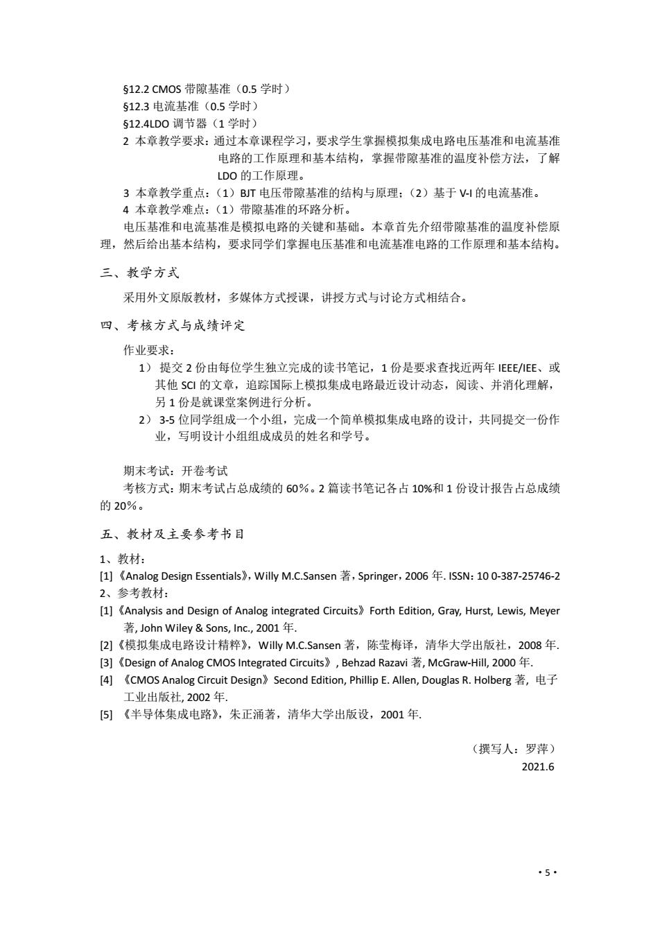
·5· §12.2 CMOS 带隙基准(0.5 学时) §12.3 电流基准(0.5 学时) §12.4LDO 调节器(1 学时) 2 本章教学要求:通过本章课程学习,要求学生掌握模拟集成电路电压基准和电流基准 电路的工作原理和基本结构,掌握带隙基准的温度补偿方法,了解 LDO 的工作原理。 3 本章教学重点:(1)BJT 电压带隙基准的结构与原理;(2)基于 V-I 的电流基准。 4 本章教学难点:(1)带隙基准的环路分析。 电压基准和电流基准是模拟电路的关键和基础。本章首先介绍带隙基准的温度补偿原 理,然后给出基本结构,要求同学们掌握电压基准和电流基准电路的工作原理和基本结构。 三、教学方式 采用外文原版教材,多媒体方式授课,讲授方式与讨论方式相结合。 四、考核方式与成绩评定 作业要求: 1) 提交 2 份由每位学生独立完成的读书笔记,1 份是要求查找近两年 IEEE/IEE、或 其他 SCI 的文章,追踪国际上模拟集成电路最近设计动态,阅读、并消化理解, 另 1 份是就课堂案例进行分析。 2) 3-5 位同学组成一个小组,完成一个简单模拟集成电路的设计,共同提交一份作 业,写明设计小组组成成员的姓名和学号。 期末考试:开卷考试 考核方式:期末考试占总成绩的 60%。2 篇读书笔记各占 10%和 1 份设计报告占总成绩 的 20%。 五、教材及主要参考书目 1、教材: [1] 《Analog Design Essentials》,Willy M.C.Sansen 著,Springer,2006 年. ISSN:10 0-387-25746-2 2、参考教材: [1]《Analysis and Design of Analog integrated Circuits》Forth Edition, Gray, Hurst, Lewis, Meyer 著, John Wiley & Sons, Inc., 2001 年. [2]《模拟集成电路设计精粹》,Willy M.C.Sansen 著,陈莹梅译,清华大学出版社,2008 年. [3]《Design of Analog CMOS Integrated Circuits》, Behzad Razavi 著, McGraw-Hill, 2000 年. [4] 《CMOS Analog Circuit Design》Second Edition, Phillip E. Allen, Douglas R. Holberg 著, 电子 工业出版社, 2002 年. [5] 《半导体集成电路》,朱正涌著,清华大学出版设,2001 年. (撰写人:罗萍) 2021.6
《模拟集成电路分析与设计》教学大纲(英文版) Course Name:Analysis and Design of Course Number: Class Hours: Analog Integrated Circuit Credits:2.5 50 0208096202 School:School of Electronic Science Students:(v)Master /(v Semester:(V)Fall/()Spring Engineering Ph.D 先修课程:Semiconductor Device,Semiconductor Technique,Basic of Analog Circuit 1.Course Objectives Analog Integrated Circuit is a most important part of IC.After learning this curriculum,the students can understand the configurations and characteristics of the elements in analog IC, handle the configurations and characteristics of the basic amplifiers,the structures and stabilities of the important amplifiers,and the system design methods of the amplifiers.Furthermore,they can handle the configurations and the basic design method of the fully-differential amplifiers, Multi-stage amplifier,the current input amplifiers,the rail to rail amplifiers,and the four kinds of feedback amplifiers.The capability in analysis and design of analog integrated circuit of the students can be trained and improved after learning this curriculum. 2.Course Content and Requirements Chapter1 Models for Integrated-Circuit Active Devices(hours:4) §1.1 PN Junction(1h) $1.2 Large-Signal and Small-Signal Models of Bipolar Transistors(1h) $1.3 Large-Signal and Small-Signal Models of MOS Transistors(1.5h) 51.4 Comparison of BJT and MOS transistors(0.5h) The keys of this chapter are the models of the active devices,including PN junction,BJT,and MOSFET.The big signal models and the small signal models of the active devices are also introduced in this chapter. The students should know how to give out the design plan according to the characteristics of the devices in ICs after learn this chapter. Chapter2 Amplifiers,Source Followers Cascodes(hours:4) 52.1 Single-transistor amplifiers(2h) S2.2 Source followers(1h) $2.3 Cascodes(2h) This chapter introduces the gains,the bandwidths,the GBWs,the big signal models and the small signal models and the AB amplifiers of the single-transistor amplifiers from the shallower to the deeper.The students should know the CL load,the output impedance,the active L of the source follower and handle the calculating methods of the output impedance and the gain of the cascodes. ·6
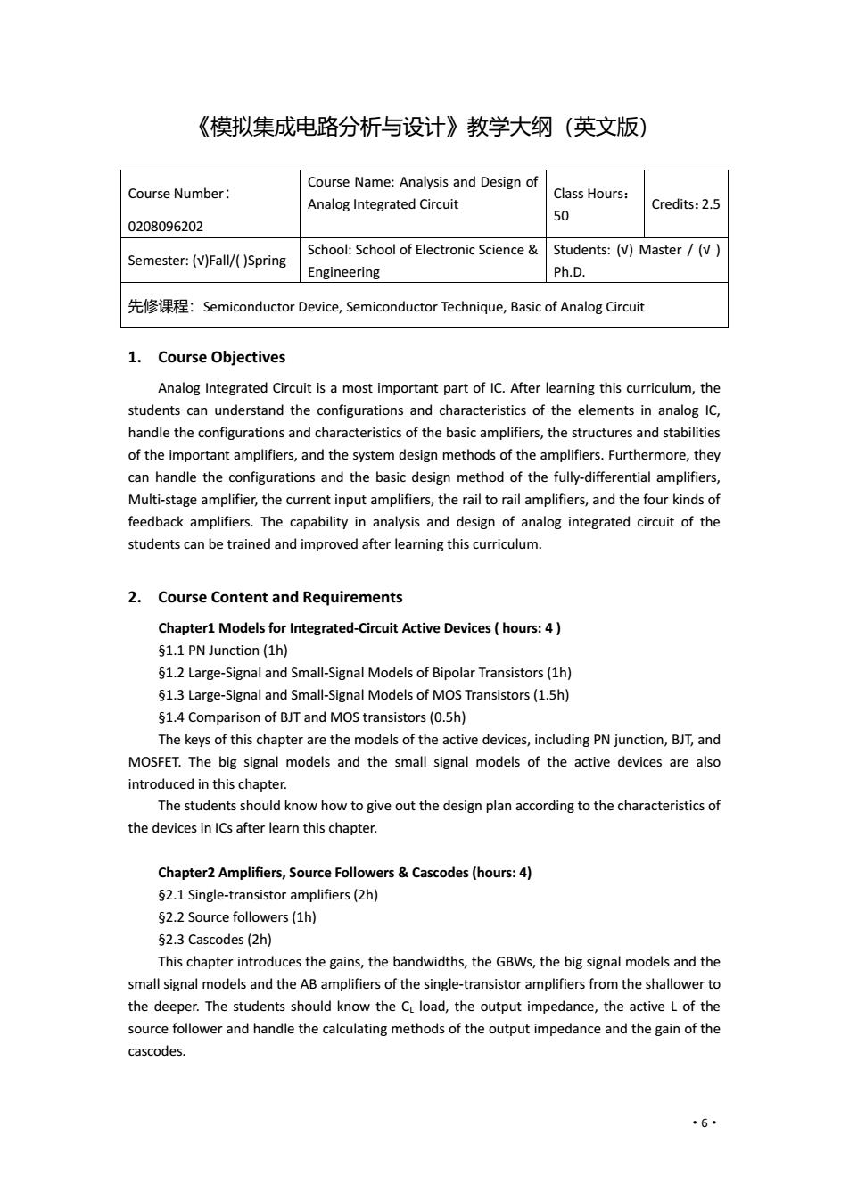
·6· 《模拟集成电路分析与设计》教学大纲(英文版) Course Number: 0208096202 Course Name: Analysis and Design of Analog Integrated Circuit Class Hours: 50 Credits:2.5 Semester: (√)Fall/( )Spring School: School of Electronic Science & Engineering Students: (√) Master / (√ ) Ph.D. 先修课程:Semiconductor Device, Semiconductor Technique, Basic of Analog Circuit 1. Course Objectives Analog Integrated Circuit is a most important part of IC. After learning this curriculum, the students can understand the configurations and characteristics of the elements in analog IC, handle the configurations and characteristics of the basic amplifiers, the structures and stabilities of the important amplifiers, and the system design methods of the amplifiers. Furthermore, they can handle the configurations and the basic design method of the fully-differential amplifiers, Multi-stage amplifier, the current input amplifiers, the rail to rail amplifiers, and the four kinds of feedback amplifiers. The capability in analysis and design of analog integrated circuit of the students can be trained and improved after learning this curriculum. 2. Course Content and Requirements Chapter1 Models for Integrated-Circuit Active Devices ( hours: 4 ) §1.1 PN Junction (1h) §1.2 Large-Signal and Small-Signal Models of Bipolar Transistors (1h) §1.3 Large-Signal and Small-Signal Models of MOS Transistors (1.5h) §1.4 Comparison of BJT and MOS transistors (0.5h) The keys of this chapter are the models of the active devices, including PN junction, BJT, and MOSFET. The big signal models and the small signal models of the active devices are also introduced in this chapter. The students should know how to give out the design plan according to the characteristics of the devices in ICs after learn this chapter. Chapter2 Amplifiers, Source Followers & Cascodes (hours: 4) §2.1 Single-transistor amplifiers (2h) §2.2 Source followers (1h) §2.3 Cascodes (2h) This chapter introduces the gains, the bandwidths, the GBWs, the big signal models and the small signal models and the AB amplifiers of the single-transistor amplifiers from the shallower to the deeper. The students should know the CL load, the output impedance, the active L of the source follower and handle the calculating methods of the output impedance and the gain of the cascodes
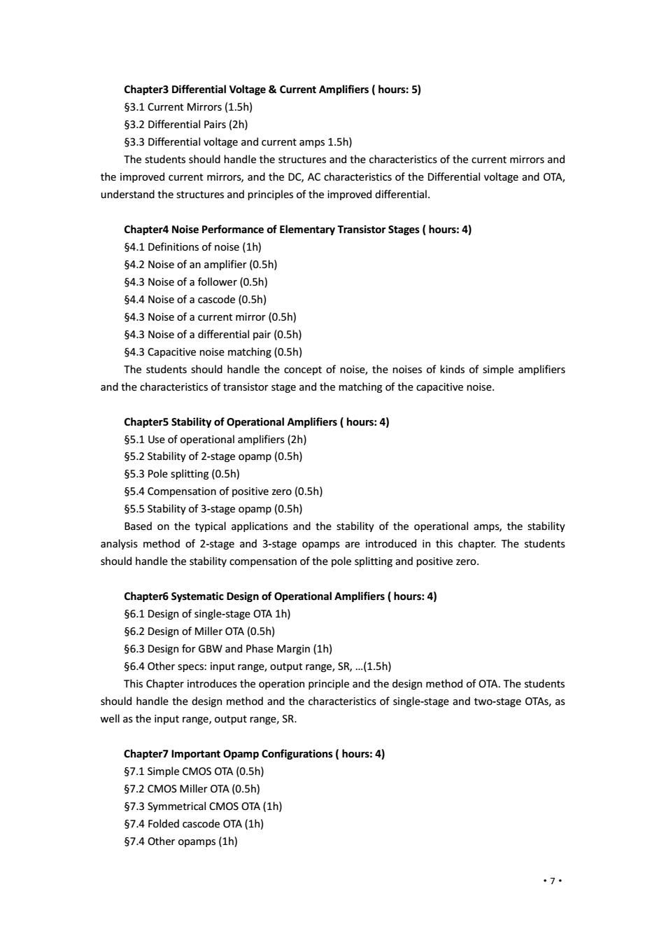
Chapter3 Differential Voltage Current Amplifiers hours:5) 53.1 Current Mirrors(1.5h) 53.2 Differential Pairs(2h) $3.3 Differential voltage and current amps 1.5h) The students should handle the structures and the characteristics of the current mirrors and the improved current mirrors,and the DC,AC characteristics of the Differential voltage and OTA, understand the structures and principles of the improved differential. Chapter4 Noise Performance of Elementary Transistor Stages(hours:4) S4.1 Definitions of noise (1h) $4.2 Noise of an amplifier(0.5h) 54.3 Noise of a follower(0.5h) 54.4 Noise of a cascode(0.5h) $4.3 Noise of a current mirror(0.5h) S4.3 Noise of a differential pair(0.5h) S4.3 Capacitive noise matching(0.5h) The students should handle the concept of noise,the noises of kinds of simple amplifiers and the characteristics of transistor stage and the matching of the capacitive noise. Chapter5 Stability of Operational Amplifiers(hours:4) S5.1 Use of operational amplifiers(2h) S5.2 Stability of 2-stage opamp(0.5h) S5.3 Pole splitting (0.5h) S5.4 Compensation of positive zero(0.5h) $5.5 Stability of 3-stage opamp(0.5h) Based on the typical applications and the stability of the operational amps,the stability analysis method of 2-stage and 3-stage opamps are introduced in this chapter.The students should handle the stability compensation of the pole splitting and positive zero. Chapter6 Systematic Design of Operational Amplifiers(hours:4) 56.1 Design of single-stage OTA 1h) 56.2 Design of Miller OTA(0.5h) $6.3 Design for GBW and Phase Margin(1h) $6.4 Other specs:input range,output range,SR,...(1.5h) This Chapter introduces the operation principle and the design method of OTA.The students should handle the design method and the characteristics of single-stage and two-stage OTAs,as well as the input range,output range,SR. Chapter7 Important Opamp Configurations(hours:4) S7.1 Simple CMOS OTA(0.5h) $7.2 CMOS Miller OTA(0.5h) 57.3 Symmetrical CMOS OTA(1h) 57.4 Folded cascode OTA(1h) §7.4 Other opamps(1h) ·7
·7· Chapter3 Differential Voltage & Current Amplifiers ( hours: 5) §3.1 Current Mirrors (1.5h) §3.2 Differential Pairs (2h) §3.3 Differential voltage and current amps 1.5h) The students should handle the structures and the characteristics of the current mirrors and the improved current mirrors, and the DC, AC characteristics of the Differential voltage and OTA, understand the structures and principles of the improved differential. Chapter4 Noise Performance of Elementary Transistor Stages ( hours: 4) §4.1 Definitions of noise (1h) §4.2 Noise of an amplifier (0.5h) §4.3 Noise of a follower (0.5h) §4.4 Noise of a cascode (0.5h) §4.3 Noise of a current mirror (0.5h) §4.3 Noise of a differential pair (0.5h) §4.3 Capacitive noise matching (0.5h) The students should handle the concept of noise, the noises of kinds of simple amplifiers and the characteristics of transistor stage and the matching of the capacitive noise. Chapter5 Stability of Operational Amplifiers ( hours: 4) §5.1 Use of operational amplifiers (2h) §5.2 Stability of 2-stage opamp (0.5h) §5.3 Pole splitting (0.5h) §5.4 Compensation of positive zero (0.5h) §5.5 Stability of 3-stage opamp (0.5h) Based on the typical applications and the stability of the operational amps, the stability analysis method of 2-stage and 3-stage opamps are introduced in this chapter. The students should handle the stability compensation of the pole splitting and positive zero. Chapter6 Systematic Design of Operational Amplifiers ( hours: 4) §6.1 Design of single-stage OTA 1h) §6.2 Design of Miller OTA (0.5h) §6.3 Design for GBW and Phase Margin (1h) §6.4 Other specs: input range, output range, SR, …(1.5h) This Chapter introduces the operation principle and the design method of OTA. The students should handle the design method and the characteristics of single-stage and two-stage OTAs, as well as the input range, output range, SR. Chapter7 Important Opamp Configurations ( hours: 4) §7.1 Simple CMOS OTA (0.5h) §7.2 CMOS Miller OTA (0.5h) §7.3 Symmetrical CMOS OTA (1h) §7.4 Folded cascode OTA (1h) §7.4 Other opamps (1h)
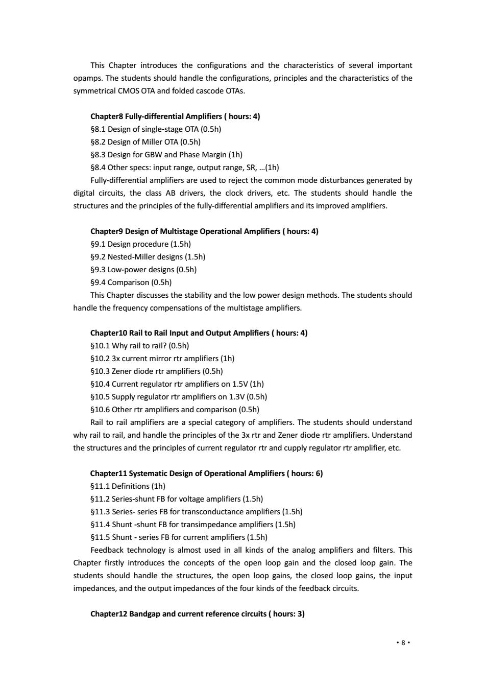
This Chapter introduces the configurations and the characteristics of several important opamps.The students should handle the configurations,principles and the characteristics of the symmetrical CMOS OTA and folded cascode OTAs. Chapter8 Fully-differential Amplifiers hours:4) 58.1 Design of single-stage OTA(0.5h) 58.2 Design of Miller OTA(0.5h) 58.3 Design for GBW and Phase Margin(1h) 58.4 Other specs:input range,output range,SR,...(1h) Fully-differential amplifiers are used to reject the common mode disturbances generated by digital circuits,the class AB drivers,the clock drivers,etc.The students should handle the structures and the principles of the fully-differential amplifiers and its improved amplifiers. Chapter9 Design of Multistage Operational Amplifiers(hours:4) 59.1 Design procedure(1.5h) 59.2 Nested-Miller designs(1.5h) 59.3 Low-power designs(0.5h) $9.4 Comparison(0.5h) This Chapter discusses the stability and the low power design methods.The students should handle the frequency compensations of the multistage amplifiers. Chapter10 Rail to Rail Input and Output Amplifiers hours:4) $10.1 Why rail to rail?(0.5h) $10.2 3x current mirror rtr amplifiers(1h) $10.3 Zener diode rtr amplifiers(0.5h) $10.4 Current regulator rtr amplifiers on 1.5V(1h) $10.5 Supply regulator rtr amplifiers on 1.3V(0.5h) $10.6 Other rtr amplifiers and comparison(0.5h) Rail to rail amplifiers are a special category of amplifiers.The students should understand why rail to rail,and handle the principles of the 3x rtr and Zener diode rtr amplifiers.Understand the structures and the principles of current regulator rtr and cupply regulator rtr amplifier,etc. Chapter11 Systematic Design of Operational Amplifiers hours:6) $11.1 Definitions(1h) $11.2 Series-shunt FB for voltage amplifiers(1.5h) $11.3 Series-series FB for transconductance amplifiers(1.5h) $11.4 Shunt-shunt FB for transimpedance amplifiers(1.5h) S11.5 Shunt-series FB for current amplifiers(1.5h) Feedback technology is almost used in all kinds of the analog amplifiers and filters.This Chapter firstly introduces the concepts of the open loop gain and the closed loop gain.The students should handle the structures,the open loop gains,the closed loop gains,the input impedances,and the output impedances of the four kinds of the feedback circuits. Chapter12 Bandgap and current reference circuits(hours:3) 8·
·8· This Chapter introduces the configurations and the characteristics of several important opamps. The students should handle the configurations, principles and the characteristics of the symmetrical CMOS OTA and folded cascode OTAs. Chapter8 Fully-differential Amplifiers ( hours: 4) §8.1 Design of single-stage OTA (0.5h) §8.2 Design of Miller OTA (0.5h) §8.3 Design for GBW and Phase Margin (1h) §8.4 Other specs: input range, output range, SR, …(1h) Fully-differential amplifiers are used to reject the common mode disturbances generated by digital circuits, the class AB drivers, the clock drivers, etc. The students should handle the structures and the principles of the fully-differential amplifiers and its improved amplifiers. Chapter9 Design of Multistage Operational Amplifiers ( hours: 4) §9.1 Design procedure (1.5h) §9.2 Nested-Miller designs (1.5h) §9.3 Low-power designs (0.5h) §9.4 Comparison (0.5h) This Chapter discusses the stability and the low power design methods. The students should handle the frequency compensations of the multistage amplifiers. Chapter10 Rail to Rail Input and Output Amplifiers ( hours: 4) §10.1 Why rail to rail? (0.5h) §10.2 3x current mirror rtr amplifiers (1h) §10.3 Zener diode rtr amplifiers (0.5h) §10.4 Current regulator rtr amplifiers on 1.5V (1h) §10.5 Supply regulator rtr amplifiers on 1.3V (0.5h) §10.6 Other rtr amplifiers and comparison (0.5h) Rail to rail amplifiers are a special category of amplifiers. The students should understand why rail to rail, and handle the principles of the 3x rtr and Zener diode rtr amplifiers. Understand the structures and the principles of current regulator rtr and cupply regulator rtr amplifier, etc. Chapter11 Systematic Design of Operational Amplifiers ( hours: 6) §11.1 Definitions (1h) §11.2 Series-shunt FB for voltage amplifiers (1.5h) §11.3 Series- series FB for transconductance amplifiers (1.5h) §11.4 Shunt -shunt FB for transimpedance amplifiers (1.5h) §11.5 Shunt - series FB for current amplifiers (1.5h) Feedback technology is almost used in all kinds of the analog amplifiers and filters. This Chapter firstly introduces the concepts of the open loop gain and the closed loop gain. The students should handle the structures, the open loop gains, the closed loop gains, the input impedances, and the output impedances of the four kinds of the feedback circuits. Chapter12 Bandgap and current reference circuits ( hours: 3)
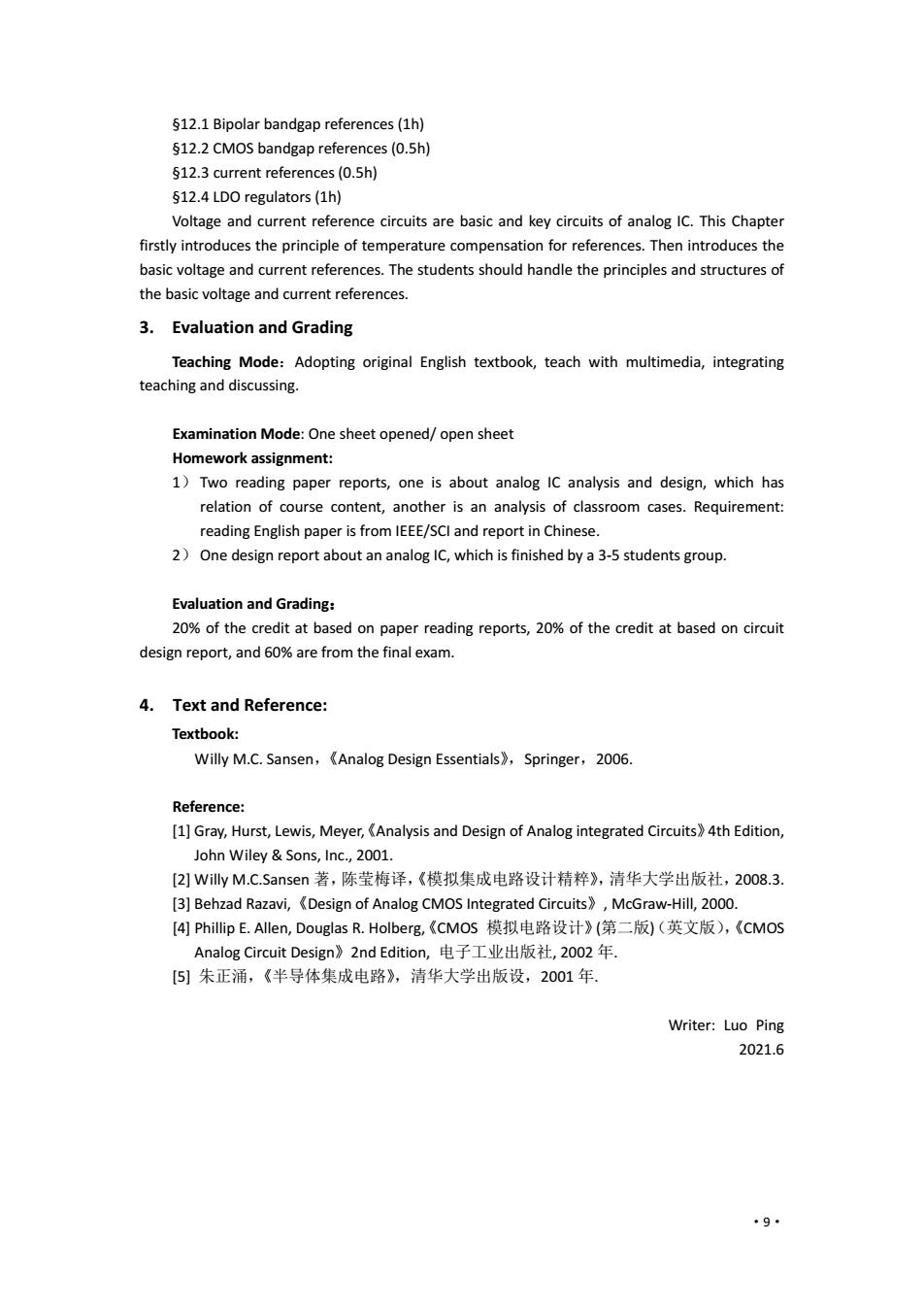
512.1 Bipolar bandgap references(1h) 512.2 CMOS bandgap references(0.5h) 512.3 current references(0.5h) $12.4 LDO regulators(1h) Voltage and current reference circuits are basic and key circuits of analog IC.This Chapter firstly introduces the principle of temperature compensation for references.Then introduces the basic voltage and current references.The students should handle the principles and structures of the basic voltage and current references. 3.Evaluation and Grading Teaching Mode:Adopting original English textbook,teach with multimedia,integrating teaching and discussing. Examination Mode:One sheet opened/open sheet Homework assignment: 1)Two reading paper reports,one is about analog IC analysis and design,which has relation of course content,another is an analysis of classroom cases.Requirement: reading English paper is from IEEE/SCI and report in Chinese. 2)One design report about an analog IC,which is finished by a 3-5 students group. Evaluation and Grading: 20%of the credit at based on paper reading reports,20%of the credit at based on circuit design report,and 60%are from the final exam. 4.Text and Reference: Textbook: Willy M.C.Sansen,Analog Design Essentials>,Springer,2006. Reference: [1]Gray,Hurst,Lewis,Meyer,Analysis and Design of Analog integrated Circuits)4th Edition, John Wiley Sons,Inc.,2001. [2]Willy M.C.Sansen著,陈莹梅译,《模拟集成电路设计精粹》,清华大学出版社,2008.3. [3]Behzad Razavi,Design of Analog CMOS Integrated Circuits,McGraw-Hill,2000. [4]Phillip E.Allen,Douglas R.Holberg,《cMos模拟电路设计》(第二版)(英文版),《cMoS Analog Circuit Design》?2 nd Edition,电子工业出版社,2002年. [5)]朱正涌,《半导体集成电路》,清华大学出版设,2001年 Writer:Luo Ping 2021.6 9
·9· §12.1 Bipolar bandgap references (1h) §12.2 CMOS bandgap references (0.5h) §12.3 current references (0.5h) §12.4 LDO regulators (1h) Voltage and current reference circuits are basic and key circuits of analog IC. This Chapter firstly introduces the principle of temperature compensation for references. Then introduces the basic voltage and current references. The students should handle the principles and structures of the basic voltage and current references. 3. Evaluation and Grading Teaching Mode:Adopting original English textbook, teach with multimedia, integrating teaching and discussing. Examination Mode: One sheet opened/ open sheet Homework assignment: 1) Two reading paper reports, one is about analog IC analysis and design, which has relation of course content, another is an analysis of classroom cases. Requirement: reading English paper is from IEEE/SCI and report in Chinese. 2) One design report about an analog IC, which is finished by a 3-5 students group. Evaluation and Grading: 20% of the credit at based on paper reading reports, 20% of the credit at based on circuit design report, and 60% are from the final exam. 4. Text and Reference: Textbook: Willy M.C. Sansen,《Analog Design Essentials》,Springer,2006. Reference: [1] Gray, Hurst, Lewis, Meyer,《Analysis and Design of Analog integrated Circuits》4th Edition, John Wiley & Sons, Inc., 2001. [2] Willy M.C.Sansen 著,陈莹梅译,《模拟集成电路设计精粹》,清华大学出版社,2008.3. [3] Behzad Razavi,《Design of Analog CMOS Integrated Circuits》, McGraw-Hill, 2000. [4] Phillip E. Allen, Douglas R. Holberg,《CMOS 模拟电路设计》(第二版)(英文版),《CMOS Analog Circuit Design》2nd Edition, 电子工业出版社, 2002 年. [5] 朱正涌,《半导体集成电路》,清华大学出版设,2001 年. Writer: Luo Ping 2021.6