Optical Spectroscopy and Instrumentation (Chapter 7) (IR,visible and UV) pathlength b concentration c Transmittance T=I 10 Percent Transmittance %T= 1×100% Io Absorbance A=-logT =-o80 I 二1og1 Examples: T=1.00(100%T),A=0.00 T=0.10(10%T),A=1.00 T=0.001(0.1%T),A=3.00 CEM 333 page 3.1
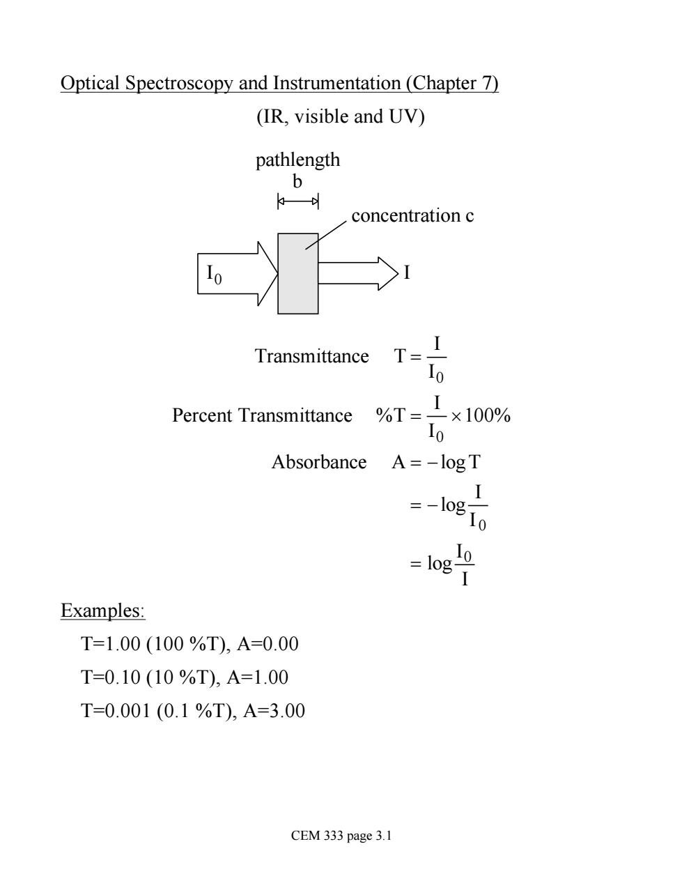
Optical Spectroscopy and Instrumentation (Chapter 7) (IR, visible and UV) I0 I pathlength b concentration c Transmittance T = I I0 Percent Transmittance %T = I I0 ´100% Absorbance A = -logT = -log I I 0 = log I0 I Examples: T=1.00 (100 %T), A=0.00 T=0.10 (10 %T), A=1.00 T=0.001 (0.1 %T), A=3.00 CEM 333 page 3.1
Beer's Law: Basis for absorbance spectrophotometry A ccc and A ocb S0Acb·c A=ab·c proportionality constant absorptivity units of L/g.cm If units of concentration are M(mol/L)then use molar absorptivity s A=8.b.c units of L/mol.cm Phenomena used for optical measurements, (1)Absorption(2)Emission (3)Luminescence (Fluorescence, Phosphorescence,Chemiluminescence(4)Scattering In all cases,response is proportional to concentration of analyte CEM 333 page 3.2
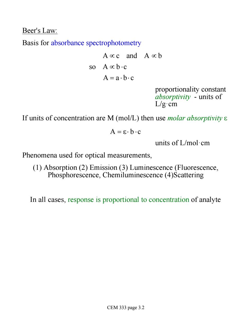
Beer's Law: Basis for absorbance spectrophotometry A µ c and A µ b so A µ b ×c A = a × b× c proportionality constant absorptivity - units of L/g·cm If units of concentration are M (mol/L) then use molar absorptivity e A = e× b ×c units of L/mol·cm Phenomena used for optical measurements, (1) Absorption (2) Emission (3) Luminescence (Fluorescence, Phosphorescence, Chemiluminescence (4)Scattering In all cases, response is proportional to concentration of analyte CEM 333 page 3.2
Many optical instruments share similar design (1)stable radiation source (2)transparent sample holder (3)wavelength selector (4)radiation detector (5)signal processor and readout Variable Solvent diaphragm cell to set 100%T %T ● Tungsten Filter Shutter Sample Photoelectric lamp cell device Fig 6-22 CEM 333 page 3.3
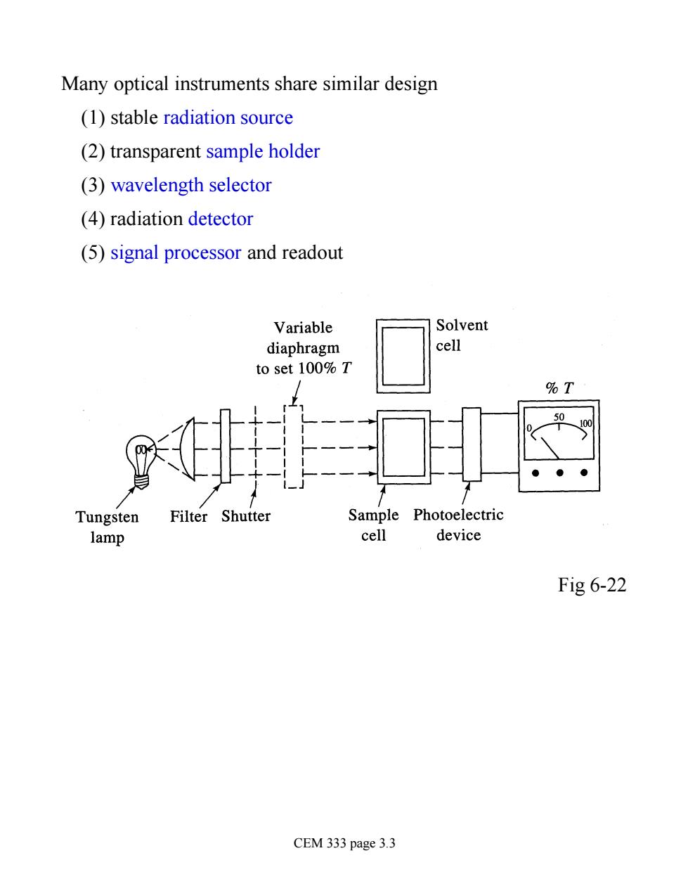
Many optical instruments share similar design (1) stable radiation source (2) transparent sample holder (3) wavelength selector (4) radiation detector (5) signal processor and readout Fig 6-22 CEM 333 page 3.3
Radiation Sources (Fig.7-3) Wavelength.nm 100 200 400 IR (a)Sources Hr Da lamp Continuur yer亿0+Y0) Nichrome wire (Ni+Cr) Globar (sic Photographic plate Photomultiplier tube Phototube Photocell Silicon diode Charge-transfer detecto Thern couple (voltage)or bolometer (resi Golay pneumatic cell CEM 333 page 3.4
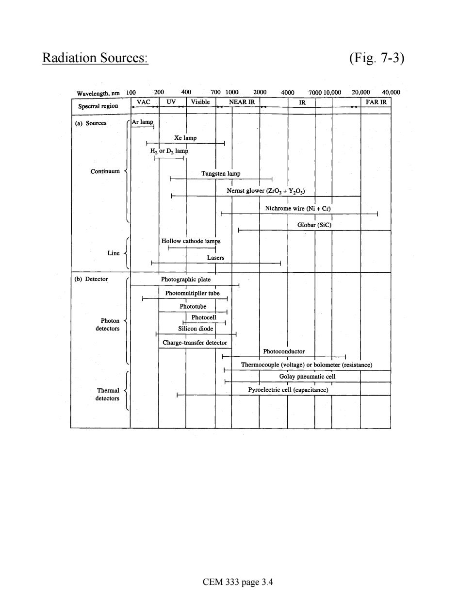
Radiation Sources: (Fig. 7-3) CEM 333 page 3.4
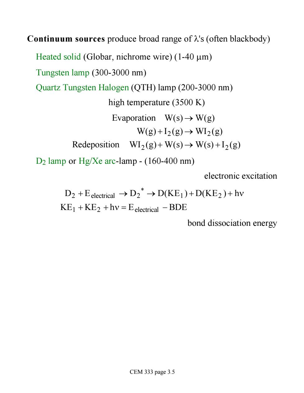
Continuum sources produce broad range of 's(often blackbody) Heated solid (Globar,nichrome wire)(1-40 um) Tungsten lamp (300-3000 nm) Quartz Tungsten Halogen (QTH)lamp(200-3000 nm) high temperature(3500 K) Evaporation W(s)->W(g) W(g)+I2(g)→W12(g) Redeposition WI2(g)+W(s)>W(s)+I2(g) D2 lamp or Hg/Xe arc-lamp -(160-400 nm) electronic excitation D2+Eelectrical→D2*-→D(KE1)+D(KE2)+hv KE1+KE2+hv=Eelectrical-BDE bond dissociation energy CEM 333 page 3.5
Continuum sources produce broad range of l's (often blackbody) Heated solid (Globar, nichrome wire) (1-40 mm) Tungsten lamp (300-3000 nm) Quartz Tungsten Halogen (QTH) lamp (200-3000 nm) high temperature (3500 K) Evaporation W(s) ® W(g) W(g) + I2 (g) ® WI2 (g) Redeposition WI2 (g)+ W(s) ® W(s) + I2 (g) D2 lamp or Hg/Xe arc-lamp - (160-400 nm) electronic excitation D2 + Eelectrical ® D2 * ® D(KE1 ) + D(KE2 ) + hn KE1 + KE2 + hn = Eelectrical - BDE bond dissociation energy CEM 333 page 3.5
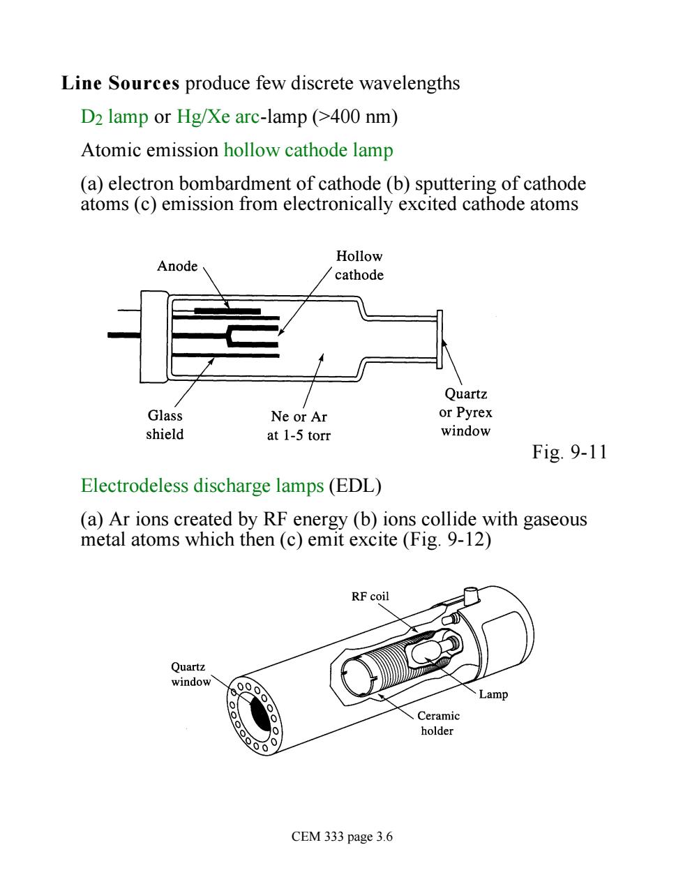
Line Sources produce few discrete wavelengths D2 lamp or Hg/Xe arc-lamp (>400 nm) Atomic emission hollow cathode lamp (a)electron bombardment of cathode (b)sputtering of cathode atoms (c)emission from electronically excited cathode atoms Hollow Anode cathode Quartz Glass Ne or Ar or Pyrex shield at 1-5 torr window Fig.9-11 Electrodeless discharge lamps(EDL) (a)Ar ions created by RF energy(b)ions collide with gaseous metal atoms which then (c)emit excite (Fig.9-12) RF coil Quartz window CEM 333 page 3.6
Line Sources produce few discrete wavelengths D2 lamp or Hg/Xe arc-lamp (>400 nm) Atomic emission hollow cathode lamp (a) electron bombardment of cathode (b) sputtering of cathode atoms (c) emission from electronically excited cathode atoms Fig. 9-11 Electrodeless discharge lamps (EDL) (a) Ar ions created by RF energy (b) ions collide with gaseous metal atoms which then (c) emit excite (Fig. 9-12) CEM 333 page 3.6
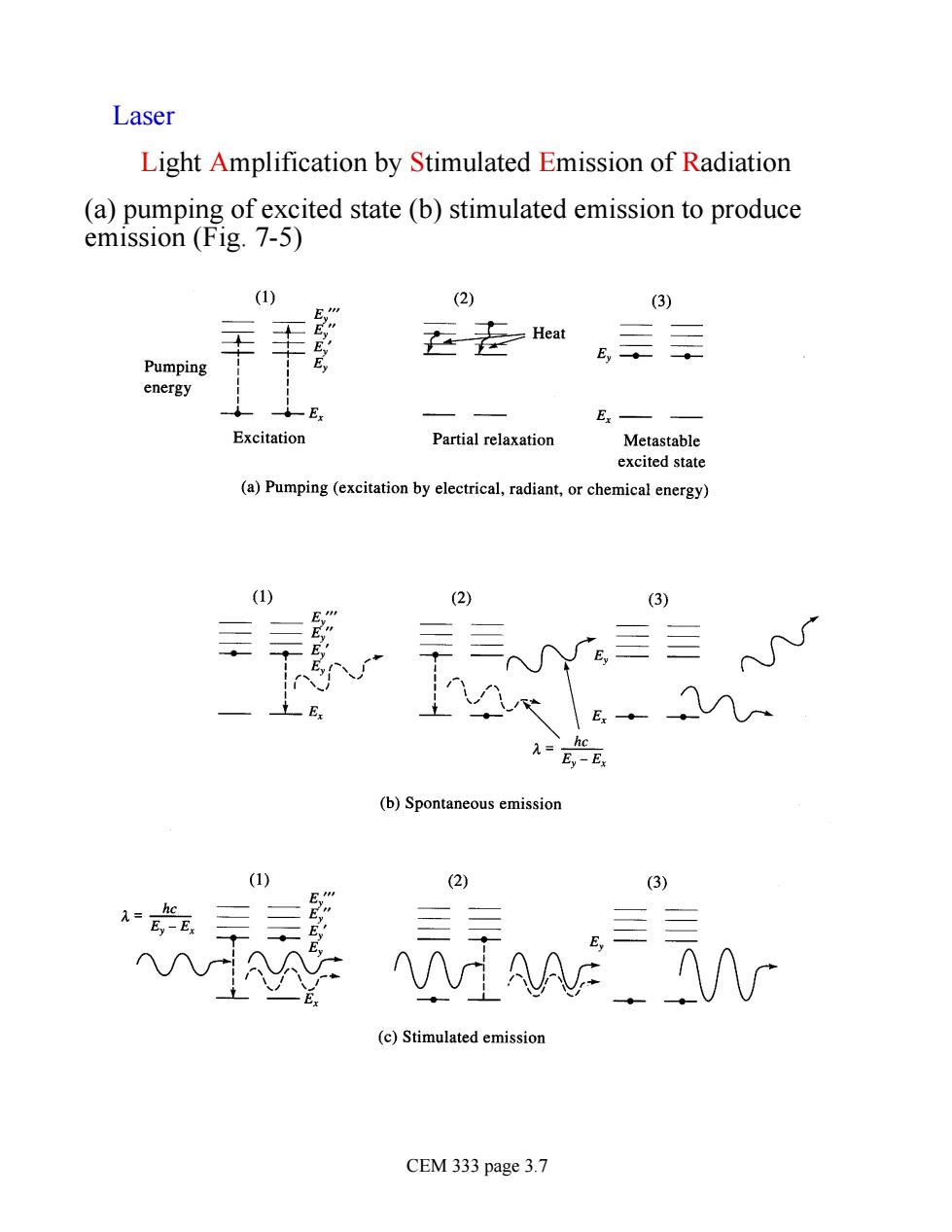
Laser Light Amplification by Stimulated Emission of Radiation (a)pumping of excited state (b)stimulated emission to produce emission (Fig.7-5) (1) (2) (3) 去去Hea Pumping energy E E Excitation Partial relaxation Metastable excited state (a)Pumping (excitation by electrical,radiant,or chemical energy) (2) (3) =E-E (b)Spontaneous emission (2) (3 (c)Stimulated emission CEM 333 page 3.7
Laser Light Amplification by Stimulated Emission of Radiation (a) pumping of excited state (b) stimulated emission to produce emission (Fig. 7-5) CEM 333 page 3.7
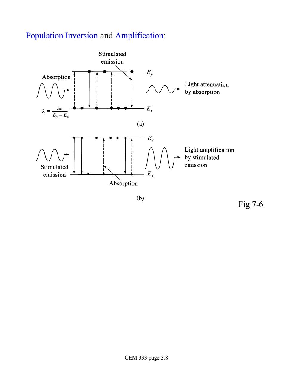
Population Inversion and Amplification: Stimulated emission Absorption Ey Light attenuation by absorption ●●● -Ex (a) Ey Light amplification by stimulated Stimulated emission emission Absorption 6 Fig 7-6 CEM 333 page 3.8
Population Inversion and Amplification: Fig 7-6 CEM 333 page 3.8
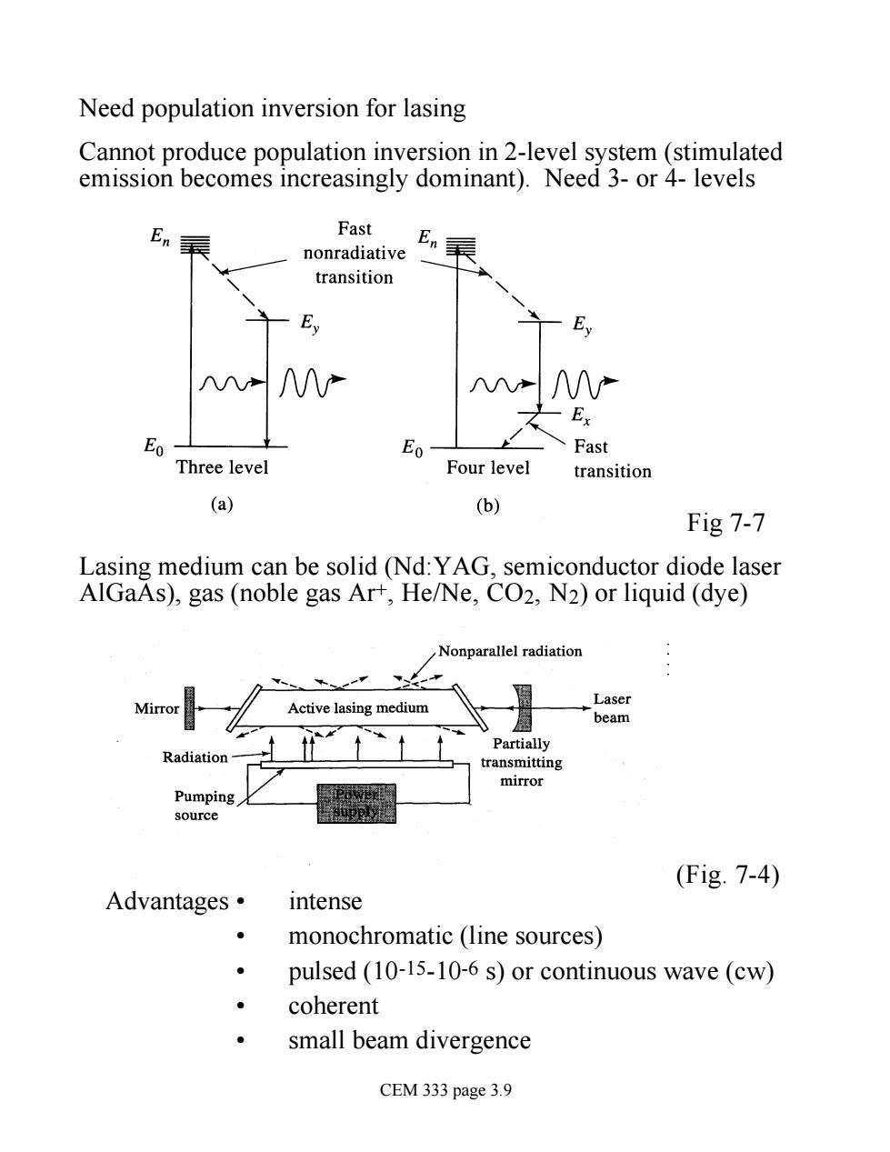
Need population inversion for lasing Cannot produce population inversion in 2-level system (stimulated emission becomes increasingly dominant).Need 3-or 4-levels En Fast En nonradiative transition ∧八 Ex Eo E01 Fast Three level Four level transition (a) (b) Fig 7-7 Lasing medium can be solid (Nd:YAG,semiconductor diode laser AlGaAs),gas(noble gas Ar+,He/Ne,CO2,N2)or liquid(dye) Nonparallel radiation . Lase Mirro Active lasing medium heam Partially Radiation transmitting mirror upply (Fig.7-4) Advantages· intense monochromatic (line sources) pulsed (10-15-10-6 s)or continuous wave(cw) coherent small beam divergence CEM 333 page 3.9
Need population inversion for lasing Cannot produce population inversion in 2-level system (stimulated emission becomes increasingly dominant). Need 3- or 4- levels Fig 7-7 Lasing medium can be solid (Nd:YAG, semiconductor diode laser AlGaAs), gas (noble gas Ar+, He/Ne, CO2, N2) or liquid (dye) (Fig. 7-4) Advantages • intense • monochromatic (line sources) • pulsed (10-15-10-6 s) or continuous wave (cw) • coherent • small beam divergence CEM 333 page 3.9

Wavelength Selectors: (Fig.7-2) Wavelength,nm 100 200 70010002000 4000700010.00020.00040.000 Spectral region VAC UV Visible NEAR IR R FAR IR (a)Ma for LE. lenses,and Fused silica or quartz prisms Corex glass Silicate glass KBr TIBr or TII Fluorite prism Fused silica or quartz prism Continuum KBr pris 3000 lines/mm Gratings 50 lines/mm Interference wedge Interference filter Discontinuous Glass fi CEM 333 page 3.10
Wavelength Selectors: (Fig. 7-2) CEM 333 page 3.10