Shaking table Test Lab Alice Salomoni 1570204 Introduction keeps on exhibiting structural models to the public as a way of public education. Briefly description about the models Shanghai International Design Center This model is the Shanghai International Design Center, which is a high-rise office building specifically for the design industry.It has a h-shape section.The architect of this building is Tadao Ando,who is the 1995 laureate of the Pritzker Prize. Kerry Jingan South Tower This model is 260 m high and is a composite structure The architect is Kohn Pedersen Fox Associates. Shanghai Financial Centre This is the shaking table model of 492m high Shanghai Financial ct is KPF and the structural engineer is Lesi perimete
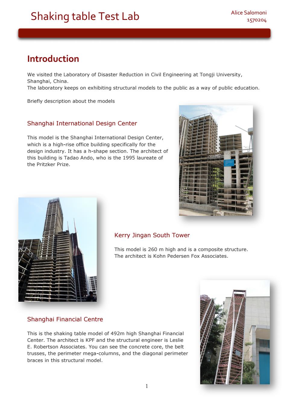
1 Alice Salomoni Shaking table Test Lab 1570204 Introduction We visited the Laboratory of Disaster Reduction in Civil Engineering at Tongji University, Shanghai, China. The laboratory keeps on exhibiting structural models to the public as a way of public education. Briefly description about the models Shanghai International Design Center This model is the Shanghai International Design Center, which is a high-rise office building specifically for the design industry. It has a h-shape section. The architect of this building is Tadao Ando, who is the 1995 laureate of the Pritzker Prize. Kerry Jingan South Tower This model is 260 m high and is a composite structure. The architect is Kohn Pedersen Fox Associates. Shanghai Financial Centre This is the shaking table model of 492m high Shanghai Financial Center. The architect is KPF and the structural engineer is Leslie E. Robertson Associates. You can see the concrete core, the belt trusses, the perimeter mega-columns, and the diagonal perimeter braces in this structural model
Shaking table Test Lab Alice Salomoni 1570204 Shanghai BOCOM Financial Tower This model are two conjoined skyscrapers which reach 265 metres in height.They are located in the Pudong District of Shanghai,China and are split into the North and South Towers.Both towers were designed by ABB Architekten.The rtn tower is the t 4th tallest existing building in the world when measured up to the highest architectural point China Pavilion This model is the China Pavilion in EXPO 2010,Shanghai.Basically,it is composed of four concrete tubes and has a steel horizontal structure on the top. Shanghai Tower This is the model of the new highest building in China, the 632m tall Shanghai Tower.The architect is Gensler and the structural engineer is Thornton Tomasetti
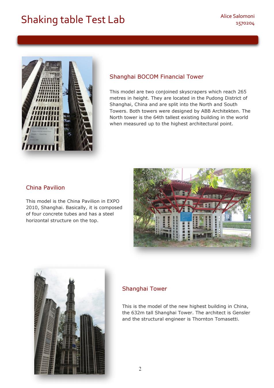
2 Shaking table Test Lab Alice Salomoni 1570204 Shanghai BOCOM Financial Tower This model are two conjoined skyscrapers which reach 265 metres in height. They are located in the Pudong District of Shanghai, China and are split into the North and South Towers. Both towers were designed by ABB Architekten. The North tower is the 64th tallest existing building in the world when measured up to the highest architectural point. China Pavilion This model is the China Pavilion in EXPO 2010, Shanghai. Basically, it is composed of four concrete tubes and has a steel horizontal structure on the top. Shanghai Tower This is the model of the new highest building in China, the 632m tall Shanghai Tower. The architect is Gensler and the structural engineer is Thornton Tomasetti
Shaking table Test Lab Alice Salomoni 1570204 Shimao International Plaza model of Shimao International Plaza,which 3m ta on the The StUctralenginersBuroHapoldconsutingEnginerS
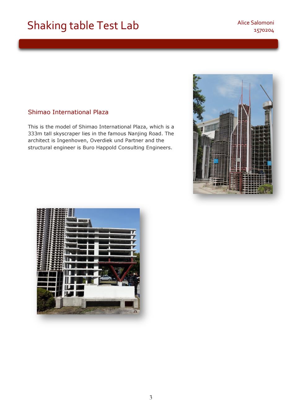
3 Alice Salomoni Shaking table Test Lab 1570204 Shimao International Plaza This is the model of Shimao International Plaza, which is a 333m tall skyscraper lies in the famous Nanjing Road. The architect is Ingenhoven, Overdiek und Partner and the structural engineer is Buro Happold Consulting Engineers
Alice Salomoni Shaking table Test Lab 1570204 The National Hall of China Pavilion for Expo 2010 1.Description of the structure aptoteEoat Shangal,China. Pudong Briefly description The China pavilion at Expo 2010 (Chinese: 中泰馆;pinyin:Zhonggu6gu6 jia guan)in Shanghai, Chi uially the (Chinese: pinyin 2 n), the lar nationa he pla histon th xpe ISs at sh ed Ch nts by After 2012,it was reopened as the China Art Museum,the largest art museum in Asia. Themes and symbolism The 63-metre high pavilion,the tallest structure at the Expo is dubbed "The Oriental Crown"because of its resemblance to an ancient Chinese crown.It was meticulously designed with profound meaning and symbolism.The architectonic feature of the building was inspired by the Chinese roof bracket known as the dougong as well as the Chinese ding vessel. The dougong is a traditional wooden bracket used to support large overhanging eaves which dates back nearly 2,000 It sy izes the charm of ing a
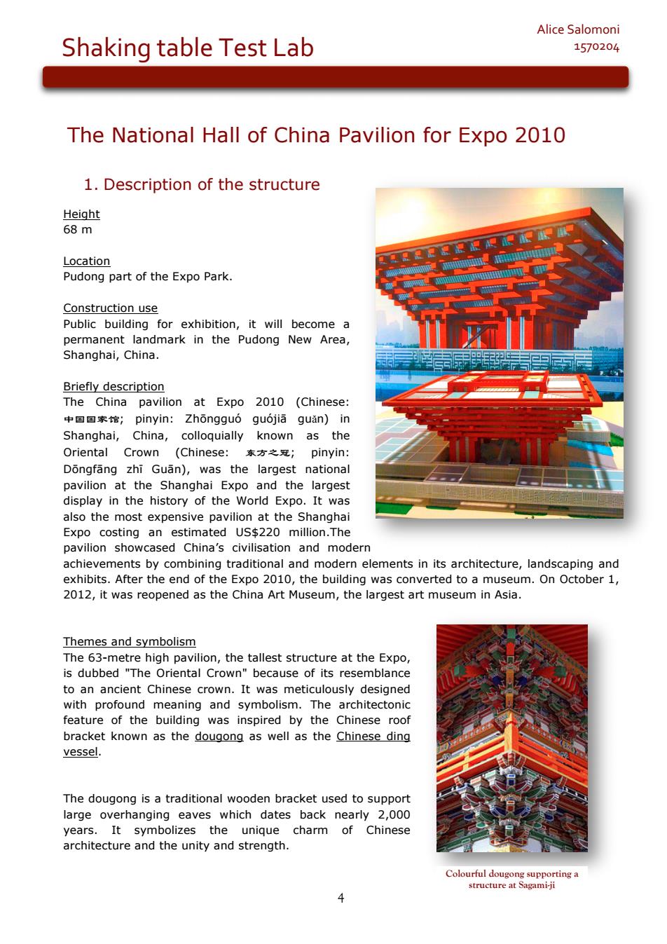
4 Alice Salomoni Shaking table Test Lab 1570204 The National Hall of China Pavilion for Expo 2010 1. Description of the structure Height 68 m Location Pudong part of the Expo Park. Construction use Public building for exhibition, it will become a permanent landmark in the Pudong New Area, Shanghai, China. Briefly description The China pavilion at Expo 2010 (Chinese: 中国国家馆; pinyin: Zhōngguó guójiā guǎn) in Shanghai, China, colloquially known as the Oriental Crown (Chinese: 东方之冠; pinyin: Dōngfāng zhī Guān), was the largest national pavilion at the Shanghai Expo and the largest display in the history of the World Expo. It was also the most expensive pavilion at the Shanghai Expo costing an estimated US$220 million.The pavilion showcased China’s civilisation and modern achievements by combining traditional and modern elements in its architecture, landscaping and exhibits. After the end of the Expo 2010, the building was converted to a museum. On October 1, 2012, it was reopened as the China Art Museum, the largest art museum in Asia. Themes and symbolism The 63-metre high pavilion, the tallest structure at the Expo, is dubbed "The Oriental Crown" because of its resemblance to an ancient Chinese crown. It was meticulously designed with profound meaning and symbolism. The architectonic feature of the building was inspired by the Chinese roof bracket known as the dougong as well as the Chinese ding vessel. The dougong is a traditional wooden bracket used to support large overhanging eaves which dates back nearly 2,000 years. It symbolizes the unique charm of Chinese architecture and the unity and strength. Colourful dougong supporting a structure at Sagami-ji
Shaking table Test Lab Alice Salomoni 1570204 S between heave eramic tripod ing Han Dynas The rooftop of the building is in the shape of a grid-like pattern reminiscent of Jiugongge when view from the air.Jiugongge was the basis of urban planning in ancient China. The exterior is painted in seven subtle shades of Chinese red,symbolizing Chinese culture and good fortune.The different shades combine effectively to illustrate the concept "unity with difference".The overhanging columns of the main China pavilion and exterior of the Chinese joint provincial pavilion are decorated with Diezhuan characters,calligraphic characters used on official seals.The characters for north,south,east and west are engraved on the red China pavilion, while 24 Chinese solar terms are carved into the silver facade of the provincial pavilion. Plan dimensions evel by eelow the height of33 mrewele crown m a m at the resulting in a de elevation,four ores top The structural system is co es with steel- resisting system.besides to sustain the vertical loads of the structure In addition at the heiaht of 33 3 m 20 inclined columns consisting of concrete-filled rectangula steel tube are placed on the perimeter of the cores as the vertical support of the big-span steel beams on the floors.Since there is no column in the interior,it satisfies the requirements of the architectural function for open and large exhibition areas
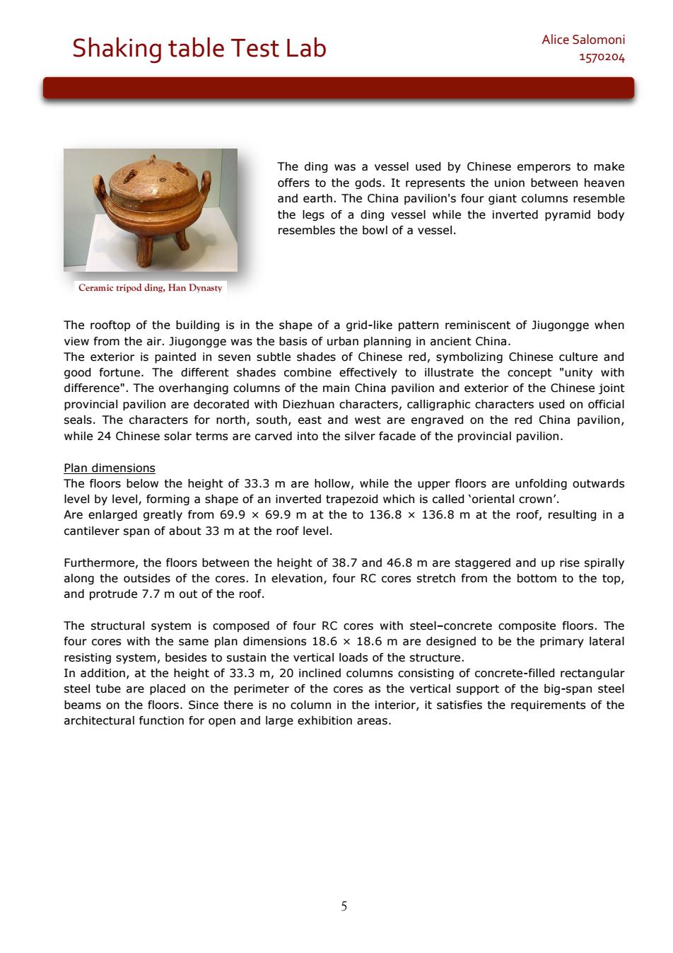
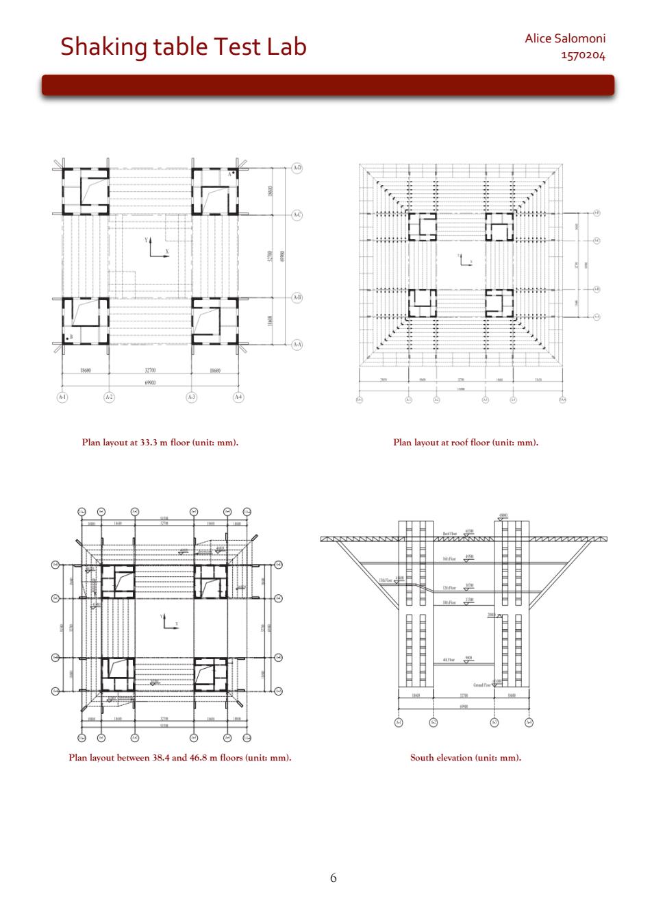
5 Alice Salomoni Shaking table Test Lab 1570204 The ding was a vessel used by Chinese emperors to make offers to the gods. It represents the union between heaven and earth. The China pavilion's four giant columns resemble the legs of a ding vessel while the inverted pyramid body resembles the bowl of a vessel. The rooftop of the building is in the shape of a grid-like pattern reminiscent of Jiugongge when view from the air. Jiugongge was the basis of urban planning in ancient China. The exterior is painted in seven subtle shades of Chinese red, symbolizing Chinese culture and good fortune. The different shades combine effectively to illustrate the concept "unity with difference". The overhanging columns of the main China pavilion and exterior of the Chinese joint provincial pavilion are decorated with Diezhuan characters, calligraphic characters used on official seals. The characters for north, south, east and west are engraved on the red China pavilion, while 24 Chinese solar terms are carved into the silver facade of the provincial pavilion. Plan dimensions The floors below the height of 33.3 m are hollow, while the upper floors are unfolding outwards level by level, forming a shape of an inverted trapezoid which is called ‘oriental crown’. Are enlarged greatly from 69.9 × 69.9 m at the to 136.8 × 136.8 m at the roof, resulting in a cantilever span of about 33 m at the roof level. Furthermore, the floors between the height of 38.7 and 46.8 m are staggered and up rise spirally along the outsides of the cores. In elevation, four RC cores stretch from the bottom to the top, and protrude 7.7 m out of the roof. The structural system is composed of four RC cores with steel–concrete composite floors. The four cores with the same plan dimensions 18.6 × 18.6 m are designed to be the primary lateral resisting system, besides to sustain the vertical loads of the structure. In addition, at the height of 33.3 m, 20 inclined columns consisting of concrete-filled rectangular steel tube are placed on the perimeter of the cores as the vertical support of the big-span steel beams on the floors. Since there is no column in the interior, it satisfies the requirements of the architectural function for open and large exhibition areas. Ceramic tripod ding, Han Dynasty
Shaking table Test Lab Alice Salomoni 1570204 lan layout at33.3m floor (unit:mm) Plan layout at roof floor (unit m L 46.8 m floors (unit mm) South elevation (unit:mm)
6 Alice Salomoni Shaking table Test Lab 1570204 Plan layout at 33.3 m floor (unit: mm). Plan layout at roof floor (unit: mm). Plan layout between 38.4 and 46.8 m floors (unit: mm). South elevation (unit: mm)

Shaking table Test Lab Alice Salomoni 1570204 2.Model design and construction 2.1.Description of the shaking table The MTS shaking table used for this test was able to input three-dimensional and six degree-of freedom motions.The table is 4 x 4 m in size.The maximum payload is 250 kN,and the maximum accelerations are 1.2,0.8 and 0.7 g in the longitudinal,transverse and vertical directions,respectively.Its working frequency ranges from 0.1 to 50 Hz,and 96 channels were available for data acquisition during testing. 2.2.Model materials and similitude relationship Micro-aggregate concrete and fine wires were used to construct the RC elements and stee wer simulated by copper plates due to its low elastic modulus and similar sto ste The moc the scalin t by scal ing down the from the prot type according e et de la scaling requirements all the str According to the dy ry there are th ree controlling scaling factors,which are independent with each c de ed accordin Given to the bearing capacity a and the size of the shaking table.the dime sion scaling factor (SI)was chosen to be 1/27 The stress scaling factor (So),which was first designed and finally determined according to the test results of material properties,was 0.143. The third controlling factor concerning acceleration (Sa)was determined to be 1.0 for the consideration of eliminating gravity distortion effect. Hence,the density scaling factor(Sp)needs to be modified using artificial mass to make up the discrepancy between the similitude-required mass and the model mass. Since the three controlling factors were chosen,the other scaling factors were obtained and listed in table below. Variable Equation Scaling factor Remark Controlling factor Elastic modulus Stress 0.143 Controlling factor S.S) 3861 1.960E-04 SS) 5196 Controlling factor (G55)P5 0193
7 Alice Salomoni Shaking table Test Lab 1570204 2. Model design and construction 2.1. Description of the shaking table The MTS shaking table used for this test was able to input three-dimensional and six degree-of freedom motions. The table is 4 × 4 m in size. The maximum payload is 250 kN, and the maximum accelerations are 1.2, 0.8 and 0.7 g in the longitudinal, transverse and vertical directions, respectively. Its working frequency ranges from 0.1 to 50 Hz, and 96 channels were available for data acquisition during testing. 2.2. Model materials and similitude relationship Micro-aggregate concrete and fine wires were used to construct the RC elements and steel structural members were simulated by copper plates due to its low elastic modulus and similar yielding properties to steel. The model was designed by scaling down the geometric properties from the prototype according to the scaling theory. Since the commercially available materials, components and loading equipment used in a test usually cannot meet all the scaling requirements simultaneously, it is hardly possible to satisfy all the similitude laws strictly. According to the dynamic similitude theory, there are three controlling scaling factors, which are independent with each other, and other scaling factors are derived accordingly. Given to the bearing capacity and the size of the shaking table, the dimension scaling factor (Sl) was chosen to be 1/27. The stress scaling factor (Sσ), which was first designed and finally determined according to the test results of material properties, was 0.143. The third controlling factor concerning acceleration (Sa) was determined to be 1.0 for the consideration of eliminating gravity distortion effect. Hence, the density scaling factor (Sρ) needs to be modified using artificial mass to make up the discrepancy between the similitude-required mass and the model mass. Since the three controlling factors were chosen, the other scaling factors were obtained and listed in table below
Shaking table Test Lab Alice Salomoni 1570204 2.3.Model construction The model structure was fabricated in the ing site adja aki g table fo the d t of the il and the pe structure.Fine wire meshes w ar assembled to simulate the reinforcement and copper plates were fabricated to mode the steel elements The concrete was placed using internal and external forms:the internal forms made use of plastic foam for easy removal,and the wood plates were applied as external forms in slipform construction. Base beam construction. The model was 2.819 m high in total, including the superstructure height of 0.0 m.An eam Afte week ere remove ing were taken out Steel beams and trusses assembling at roof level. 3.Test programme 3.1.Model installation The model was hoisted by a crane and placed at the centre of the shaking table.To ensure an effective transmission of the table motion to the model,the model base beam was firmly mounted on the shaking table through bolt connections
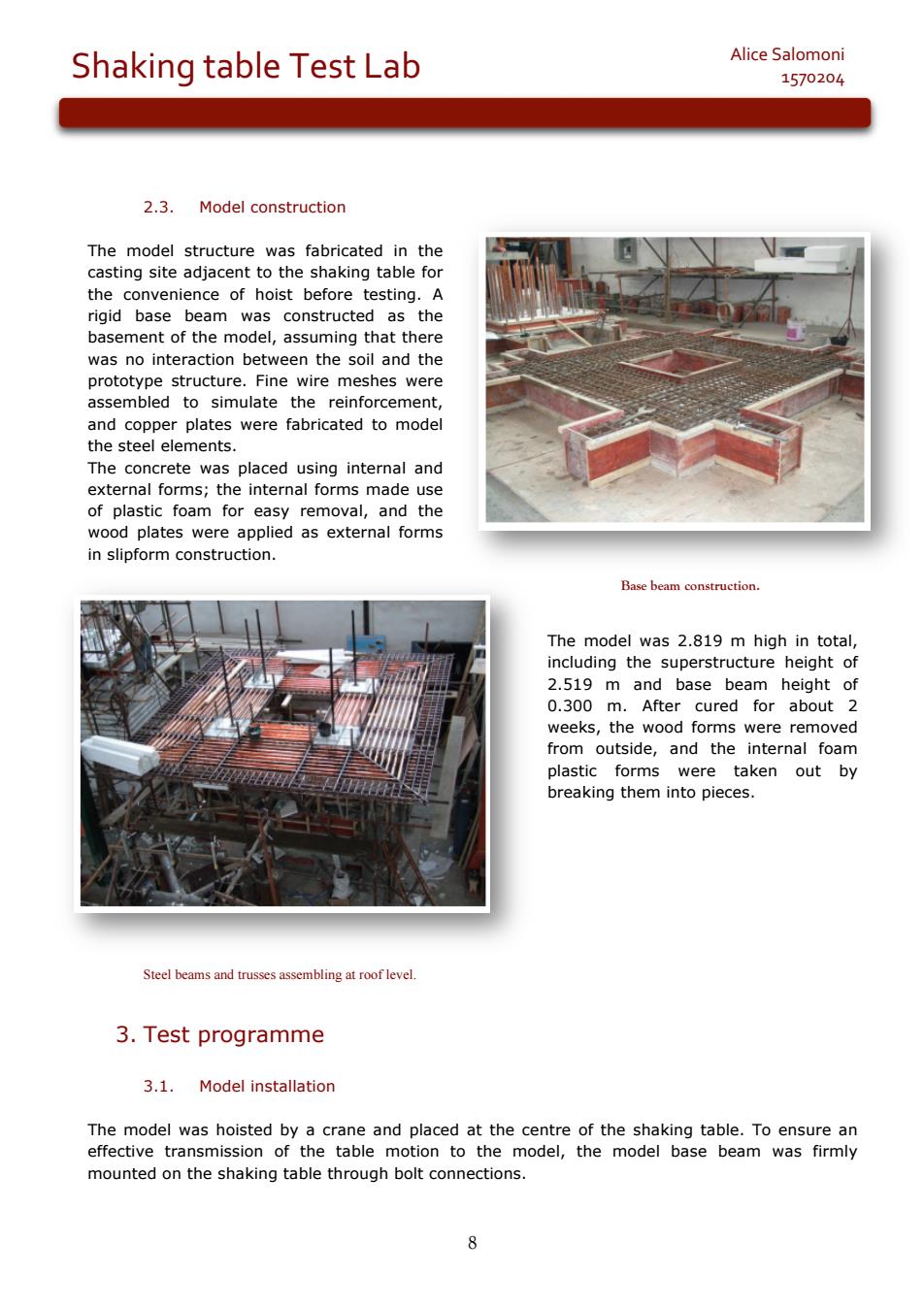
8 Alice Salomoni Shaking table Test Lab 1570204 2.3. Model construction The model structure was fabricated in the casting site adjacent to the shaking table for the convenience of hoist before testing. A rigid base beam was constructed as the basement of the model, assuming that there was no interaction between the soil and the prototype structure. Fine wire meshes were assembled to simulate the reinforcement, and copper plates were fabricated to model the steel elements. The concrete was placed using internal and external forms; the internal forms made use of plastic foam for easy removal, and the wood plates were applied as external forms in slipform construction. Base beam construction. The model was 2.819 m high in total, including the superstructure height of 2.519 m and base beam height of 0.300 m. After cured for about 2 weeks, the wood forms were removed from outside, and the internal foam plastic forms were taken out by breaking them into pieces. Steel beams and trusses assembling at roof level. 3. Test programme 3.1. Model installation The model was hoisted by a crane and placed at the centre of the shaking table. To ensure an effective transmission of the table motion to the model, the model base beam was firmly mounted on the shaking table through bolt connections
Shaking table Test Lab Alice Salomoni 1570204 and disks were useda sto make up the discrepancy between the requrednd the model mrnude relationship. These weights aonmg3soaewngo each to the rotot The 上海世博会中国馆国家馆擦合 model was calculated to he 16 49 tons,and the total mass on the table including the artificial mass and the mass of the model,was estimated to be 24.78 tons. Shown in figure is an overview of the model with artificial mass after installation on the shaking table. ivid ha Overvicw of the model on shaking table 3.2. Instrumentation Three types of instrumentations: 。 accelerometers Displacement transducers ·Strain gauges. Were installed on the model so that both the global and local responses of interest could be measured.The distribution of the accelerometers and the displacement transducers is shown in figure below,where letters A and D refer to accelerometer and displacement transducer, respectively
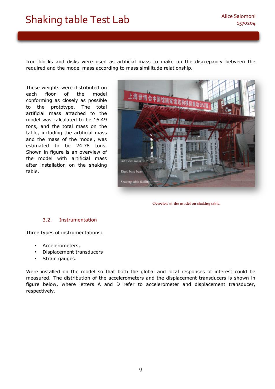
9 Alice Salomoni Shaking table Test Lab 1570204 Iron blocks and disks were used as artificial mass to make up the discrepancy between the required and the model mass according to mass similitude relationship. These weights were distributed on each floor of the model conforming as closely as possible to the prototype. The total artificial mass attached to the model was calculated to be 16.49 tons, and the total mass on the table, including the artificial mass and the mass of the model, was estimated to be 24.78 tons. Shown in figure is an overview of the model with artificial mass after installation on the shaking table. Overview of the model on shaking table. 3.2. Instrumentation Three types of instrumentations: • Accelerometers, • Displacement transducers • Strain gauges. Were installed on the model so that both the global and local responses of interest could be measured. The distribution of the accelerometers and the displacement transducers is shown in figure below, where letters A and D refer to accelerometer and displacement transducer, respectively

Shaking table Test Lab Alice Salomoni 1570204 Arrangement of accelerometers and displacement transducers 45 accelerometers used to monitor the acceleration responses of the model. The displacement can also be obtained by integrating the recorded acceleration twice n the base b a m to check the table input, to mea cele were distributed sihle Taking the 10th floor(corresponding to the height of 33.3 m)as an example 3 accelerometers were placed at a corner of one rc core in the directions of x.y and z of the two orizontalirein er s at the thepit core for the measurement of torsional effect on this floor 12 displacement transducers placed at the base beam,as well as the perimeter of the cantilever floors,for the purpose of monitoring the maximum floor displacements. 15 strain gauges were concentrated on members whose stresses are of interest,such as the inclined columns,the bottom of the RC core,the steel beams and the trusses both at top and bottom chords,where the local behaviour was of particular interest
10 Alice Salomoni Shaking table Test Lab 1570204 Arrangement of accelerometers and displacement transducers 45 accelerometers used to monitor the acceleration responses of the model. The displacement can also be obtained by integrating the recorded acceleration twice. • 3 accelerometers on the base beam to check the table input, • 4 at the perimeter of the roof level to measure the maximum accelerations, • other accelerometers were distributed on floors along the height of the RC cores as uniformly as possible. Taking the 10th floor (corresponding to the height of 33.3 m) as an example, • 3 accelerometers were placed at a corner of one RC core in the directions of X, Y and Z of the shaking table, respectively; • 2 accelerometers along the two horizontal directions were set at the corner of the opposite core for the measurement of torsional effect on this floor. • 12 displacement transducers placed at the base beam, as well as the perimeter of the cantilever floors, for the purpose of monitoring the maximum floor displacements. • 15 strain gauges were concentrated on members whose stresses are of interest, such as the inclined columns, the bottom of the RC core, the steel beams and the trusses both at top and bottom chords, where the local behaviour was of particular interest