Bagatti Alessia-1436375 Preliminary design of beams and columns Tall building structures Tongji University A.Y.2014/2015
Bagatti Alessia - 1436375 A.Y. 2014/2015 Preliminary design of beams and columns Tall building structures Tongji University
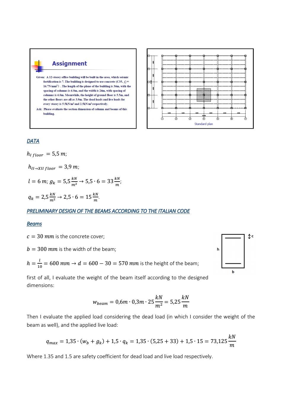
Assignment of and beams of th时 DATA hi ftoor =5,5 mi hi-xI toor 3,9 m: l=6m:9k=5,5祭-556=33签 qk=2,5→2,5·6=15 PRELIMINARY DESIGN OF THE BEAMS ACCORDING TO THE ITALIAN CODE Beams c=30 mm is the concrete cover; b=300mm is the width of the beam; h=600mmd600-30=570 mm is the height of the beam; first of all,I evaluate the weight of the beam itself according to the designed dimensions: wm=06m-03m:25°=525兴 Then I evaluate the applied load considering the dead load(in which I consider the weight of the beam as well),and the applied live load: F135·w+9)+15·9=1355,25+33)+15·15=731 Where 1.35 and 1.5 are safety coefficient for dead load and live load respectively
DATA ; ; ; ; . PRELIMINARY DESIGN OF THE BEAMS ACCORDING TO THE ITALIAN CODE Beams is the concrete cover; is the width of the beam; is the height of the beam; first of all, I evaluate the weight of the beam itself according to the designed dimensions: Then I evaluate the applied load considering the dead load (in which I consider the weight of the beam as well), and the applied live load: Where 1.35 and 1.5 are safety coefficient for dead load and live load respectively
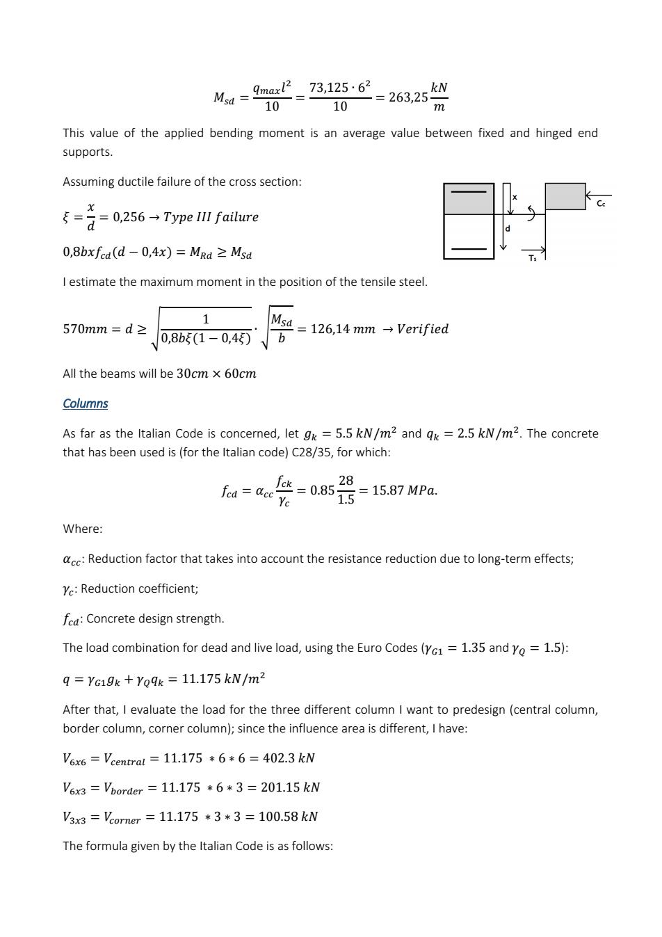
Ma=20-7315=26325州 10 This value of the applied bending moment is an average value between fixed and hinged end supports. Assuming ductile failure of the cross section: 5-音=0256→Type I fatbre 0,8bxfea(d-0,4x)=Mga 2 Msa I estimate the maximum moment in the position of the tensile steel 1 570mm=d≥ 0,8b1-0,45万 =126,14mm→Verified All the beams will be 30cm x 60cm Columns As far as the Italian Code is concerned,let gk =5.5 kN/m2 and qk=2.5 kN/m2.The concrete that has been used is(for the Italian code)C28/35,for which: a=袋=08s-1587w Ye Where: :Reduction factor that takes into account the resistance reduction due to long-term effects; Y:Reduction coefficient; fe:Concrete design strength. The load combination for dead and live load,using the Euro Codes(Yc=1.35 and Yo=1.5): q=YG19x+Yoqx 11.175 kN/m2 After that,I evaluate the load for the three different column I want to predesign(central column border column,corner column);since the influence area is different,I have: V%x6=Vcentral=11.175*6*6=402.3kW V6x3=Vporder=11.175*6*3=201.15kW V33=omer=11.175*3*3=100.58kW The formula given by the Italian Code is as follows
This value of the applied bending moment is an average value between fixed and hinged end supports. Assuming ductile failure of the cross section: I estimate the maximum moment in the position of the tensile steel. All the beams will be Columns As far as the Italian Code is concerned, let and . The concrete that has been used is (for the Italian code) C28/35, for which: Where: : Reduction factor that takes into account the resistance reduction due to long-term effects; : Reduction coefficient; : Concrete design strength. The load combination for dead and live load, using the Euro Codes ( and ): After that, I evaluate the load for the three different column I want to predesign (central column, border column, corner column); since the influence area is different, I have: The formula given by the Italian Code is as follows:

N Where the design strength of the concrete has been reduced of 50%less,N is the axial force applied to the column,and l.min is the minimum width of the column. Note that also in the Italian Code,the value of N need to be incremented by a factor B,which considers the position of the column in the structure itself(whether the column is central,on the sides or on the corners) Central column:B=1.0; Side column:B 1.1;B =1.2. In the evaluation of the weights,I considered also the parts of beams coming into the columns(i.e. 12 metres of beams for the central column,9 metres for the side columns and 6 metres for the corner columns). Here as follows the weights of the single floors have been computed on the way down,summing up the weights coming from the upper levels: WEIGHTS Floor Central column [kN] Side column [kN] Corner column [kN] 12 456.3 261.765 147.69 11 912.6 523.53 295.38 10 1368,9 785,299 443,0 9 1825.2 1047.06 590.76 22815 1308825 738.45 2737,8 1570,59 886,14 6 3194,1 1832.355 1033.83 3650,4 2094,12 1181,52 4106,7 2355,885 1329,21 4563 2617.65 1476.9 5019,3 2879,415 1624,59 5475.6 3141,18 1772.28 Here as follows are the minimum width of the column cross section,evaluated as written before: WIDTHS Floor Central column [mm] Side column [mm] Corner column [mm] 12 239,8014 181,6278 136.4275 11 339,1304 256,8605 192,9377 415,3483 314,5886 236,2994 9 479,6029 363,2556 272,8551
Where the design strength of the concrete has been reduced of 50% less, N is the axial force applied to the column, and is the minimum width of the column. Note that also in the Italian Code, the value of N need to be incremented by a factor , which considers the position of the column in the structure itself (whether the column is central, on the sides or on the corners): Central column: ; Side column: ; In the evaluation of the weights, I considered also the parts of beams coming into the columns (i.e. 12 metres of beams for the central column, 9 metres for the side columns and 6 metres for the corner columns). Here as follows the weights of the single floors have been computed on the way down, summing up the weights coming from the upper levels: Here as follows are the minimum width of the column cross section, evaluated as written before: WIDTHS Floor Central column [mm] Side column [mm] Corner column [mm] 12 239,8014 181,6278 136,4275 11 339,1304 256,8605 192,9377 10 415,3483 314,5886 236,2994 9 479,6029 363,2556 272,8551 WEIGHTS Floor Central column [kN] Side column [kN] Corner column [kN] 12 456,3 261,765 147,69 11 912,6 523,53 295,38 10 1368,9 785,295 443,07 9 1825,2 1047,06 590,76 8 2281,5 1308,825 738,45 7 2737,8 1570,59 886,14 6 3194,1 1832,355 1033,83 5 3650,4 2094,12 1181,52 4 4106,7 2355,885 1329,21 3 4563 2617,65 1476,9 2 5019,3 2879,415 1624,59 G 5475,6 3141,18 1772,28
5362123 4061321 305,0613 > 587,3911 444,8954 334,1779 6 634,4549 480,542 360,9534 678.2609 513.721 385.8754 4 719,4043 544,8834 409,2826 3 758.3187 574.3575 431.4218 795.3314 602.3913 452.479 G 830,6965 629,1772 472,5989 Starting from the previous table,the width of the column has been evaluated as follows: WIDTHS Central column [mm] Side column [mml Corner column [mm] 12 300 300 300 00 300 10 50 300 500 400 300 600 7 600 500 400 6 700 500 400 54 700 600 400 800 600 400 800 600 500 2 600 500 850 650 500
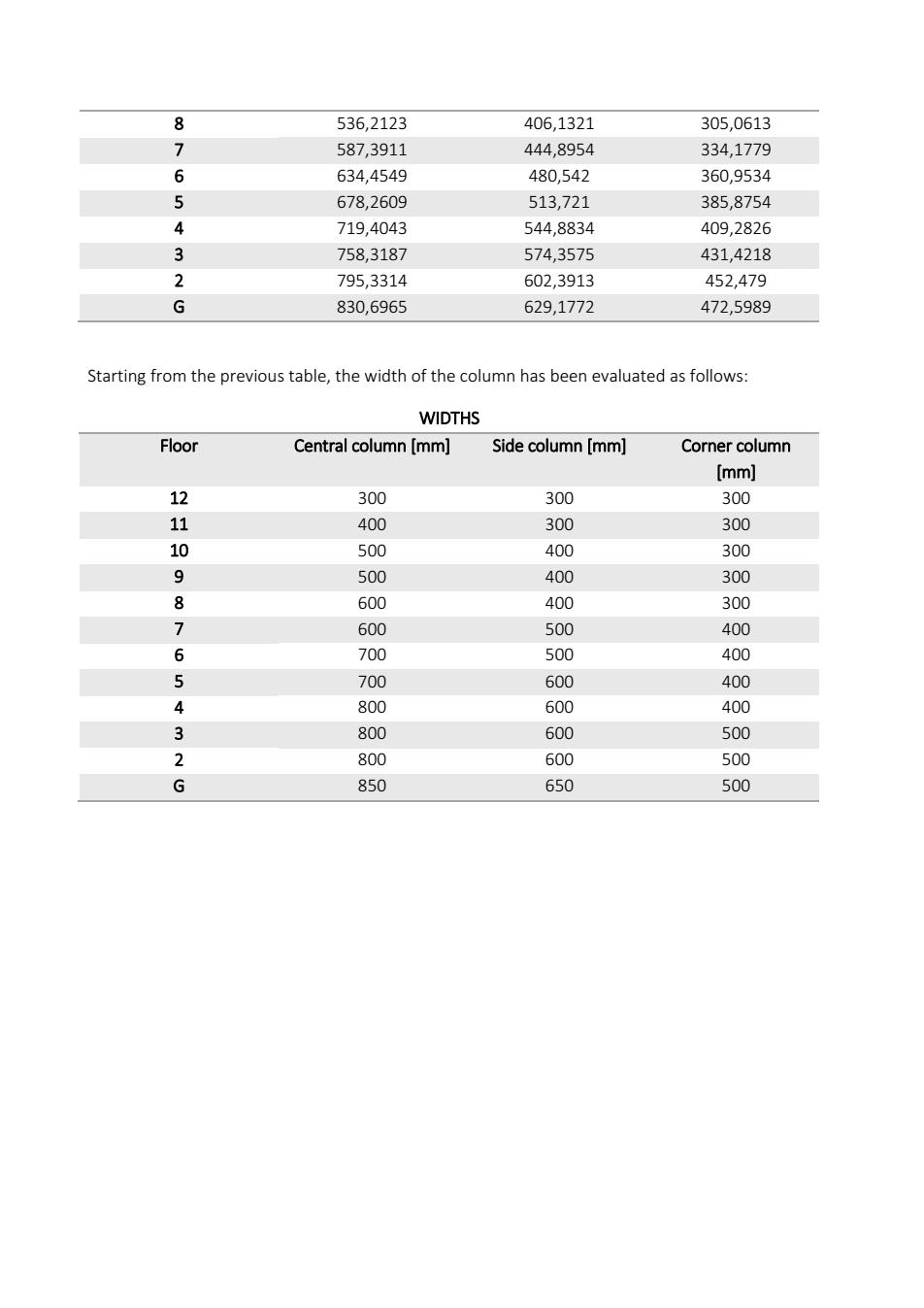
8 536,2123 406,1321 305,0613 7 587,3911 444,8954 334,1779 6 634,4549 480,542 360,9534 5 678,2609 513,721 385,8754 4 719,4043 544,8834 409,2826 3 758,3187 574,3575 431,4218 2 795,3314 602,3913 452,479 G 830,6965 629,1772 472,5989 Starting from the previous table, the width of the column has been evaluated as follows: WIDTHS Floor Central column [mm] Side column [mm] Corner column [mm] 12 300 300 300 11 400 300 300 10 500 400 300 9 500 400 300 8 600 400 300 7 600 500 400 6 700 500 400 5 700 600 400 4 800 600 400 3 800 600 500 2 800 600 500 G 850 650 500
PRELIMINARY DESIGN ACCORDING TO THE CHINESE CODE Beams The spam of the beam determines the height of the girder A,-后0司L-60m b=0引a-30m All the beams will be 30cm x 60cm Columns As far as the Chinese GB 50011-2010 is concerned,the evaluation can be done in the same way, with different coefficients.The C35 concrete has af=16.7 MPa,according to the Chinese code, whereas Yc=1.2 and Yo=1.4;given that q=YG19x Yoqx=10.1 kN/m2 After that,I evaluate the load for the three different column I want to predesign(central column, border column,corner colum);since the influence area is different,I have: V6x6=Vcentral=10.1*6*6=372.6kW V6x3=Vborder=10.1*6*3=186.3kW V33=Veorner=10.1*3*3=93.15kW The evaluation if the minimum width of the column cross section is again N Where the design strength of the concrete has been reduced of a coefficient u=0.75,N is the axial force applied to the column,and gin is the minimum width of the column. Note that in the chinese code as well the value of n need to be incremented by a factor 8.which considers the position of the column in the structure itself(whether the column is central,on the sides or on the corners): Central column:B=1.0; Side column:B 1.1;B =1.2 There will be used two other coefficients to take into account the seismic loads requested (c=1.05):
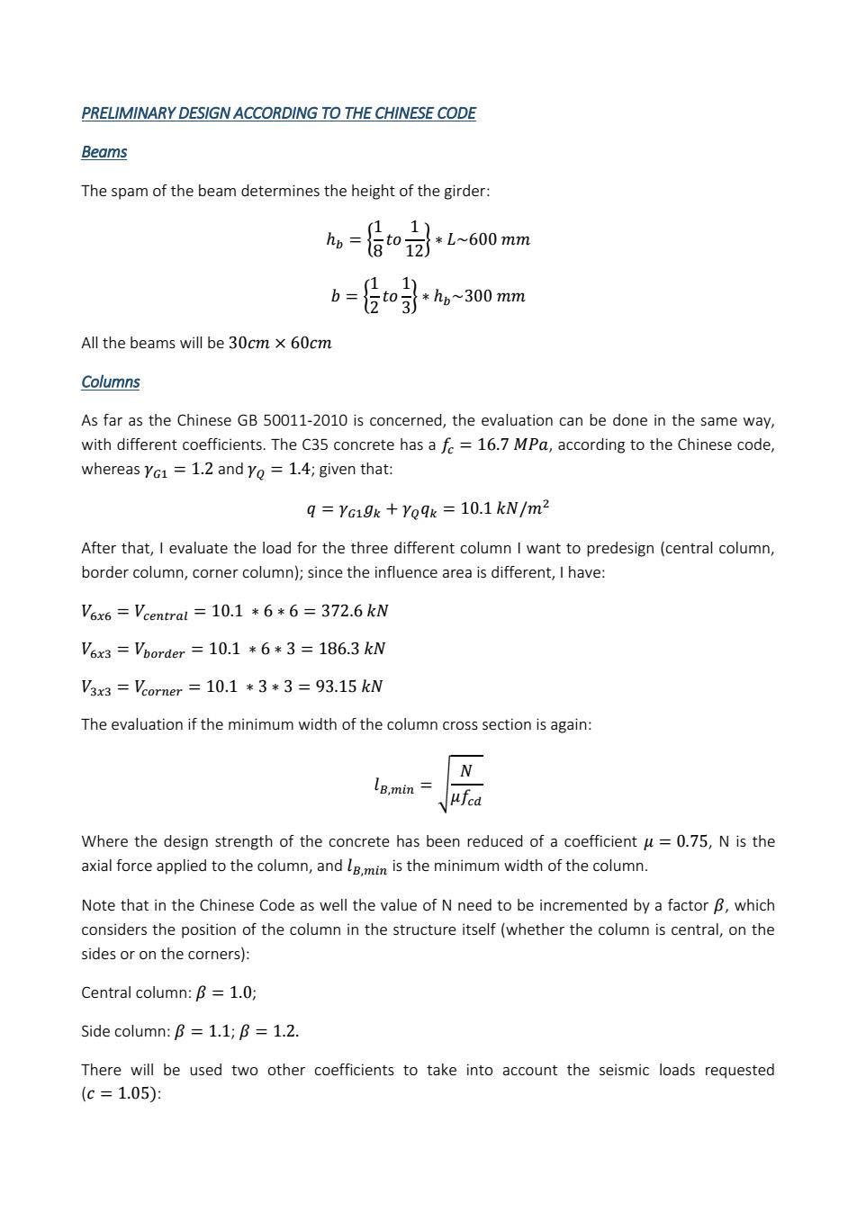
PRELIMINARY DESIGN ACCORDING TO THE CHINESE CODE Beams The spam of the beam determines the height of the girder: All the beams will be Columns As far as the Chinese GB 50011-2010 is concerned, the evaluation can be done in the same way, with different coefficients. The C35 concrete has a , according to the Chinese code, whereas and ; given that: After that, I evaluate the load for the three different column I want to predesign (central column, border column, corner column); since the influence area is different, I have: The evaluation if the minimum width of the column cross section is again: Where the design strength of the concrete has been reduced of a coefficient , N is the axial force applied to the column, and is the minimum width of the column. Note that in the Chinese Code as well the value of N need to be incremented by a factor , which considers the position of the column in the structure itself (whether the column is central, on the sides or on the corners): Central column: ; Side column: ; There will be used two other coefficients to take into account the seismic loads requested ( :
Not=1.25·c…B·V Whether the applied load is related to the central column,the side column or the corner column. In the evaluation of the weights,also in this case I considered also the parts of beams coming into the columns (i.e.12 metres of beams for the central column,9 metres for the side columns and 6 metres for the corner columns). Here as follows the weights of the single floors have been computed on the way down,summing up the weights coming from the upper levels: WEIGHTS Floor Central column [kN] Side column [kN] Corner column [kN] 12 559,9125 322,1269 182,1488 11 1119.825 644.2538 364.2975 1679,738 966,3806 546,4463 9 2239.65 1288,508 728.595 2799.563 1610.634 910.7438 3359,475 1932,761 1092,893 6 3919,388 2254.888 1275.041 4479.3 2577.015 1457.19 5039,213 2899,14 1639,339 5599.125 3221.269 1821488 6159038 3543396 2003636 6718,95 3865,523 2185,785 Here as follows are the minimum width of the column cross section,evaluated as written before: WIDTHS Floor Central column [mm] Side column [mm] Corner column [mm] 12 211.4322 160,3705 120,5936 11 299.0103 226,7982 170,5451 10 366,2114 277,7699 208,874 9 422.8645 320,7411 2411872 87 472,7769 358,.5994 269,6555 517,9011 392,826 295,3928 6 559.3971 424.3006 319.0607 5 598,0207 453,5964 341,0902 634.2967 481.1116 361.7808 668.6075 507.1362 3813504 2 701,2414 531,8889 399.9637
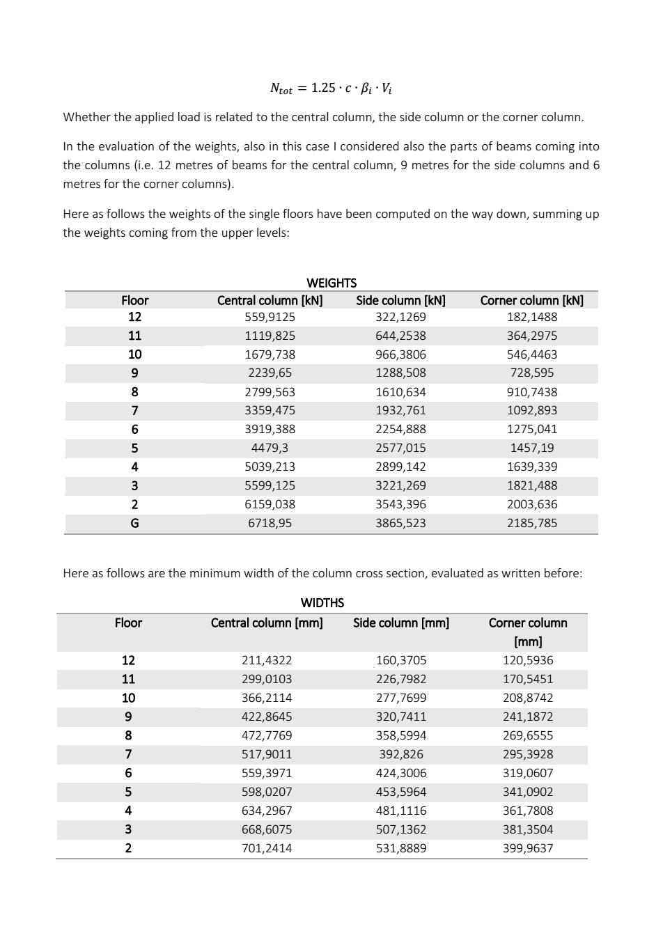
Whether the applied load is related to the central column, the side column or the corner column. In the evaluation of the weights, also in this case I considered also the parts of beams coming into the columns (i.e. 12 metres of beams for the central column, 9 metres for the side columns and 6 metres for the corner columns). Here as follows the weights of the single floors have been computed on the way down, summing up the weights coming from the upper levels: Here as follows are the minimum width of the column cross section, evaluated as written before: WIDTHS Floor Central column [mm] Side column [mm] Corner column [mm] 12 211,4322 160,3705 120,5936 11 299,0103 226,7982 170,5451 10 366,2114 277,7699 208,8742 9 422,8645 320,7411 241,1872 8 472,7769 358,5994 269,6555 7 517,9011 392,826 295,3928 6 559,3971 424,3006 319,0607 5 598,0207 453,5964 341,0902 4 634,2967 481,1116 361,7808 3 668,6075 507,1362 381,3504 2 701,2414 531,8889 399,9637 WEIGHTS Floor Central column [kN] Side column [kN] Corner column [kN] 12 559,9125 322,1269 182,1488 11 1119,825 644,2538 364,2975 10 1679,738 966,3806 546,4463 9 2239,65 1288,508 728,595 8 2799,563 1610,634 910,7438 7 3359,475 1932,761 1092,893 6 3919,388 2254,888 1275,041 5 4479,3 2577,015 1457,19 4 5039,213 2899,142 1639,339 3 5599,125 3221,269 1821,488 2 6159,038 3543,396 2003,636 G 6718,95 3865,523 2185,785
732,4228 555,5399 417,7485 Starting from the previous table,the width of the column has been evaluated as follows WIDTHS Floor Central column [mm] Side column [mm] Corner column [mm] 12 300 300 300 300 300 300 0 400 300 300 500 400 300 500 400 300 600 400 300 65 600 500 400 600 500 400 700 500 400 32 700 500 400 700 600 400 750 600 450
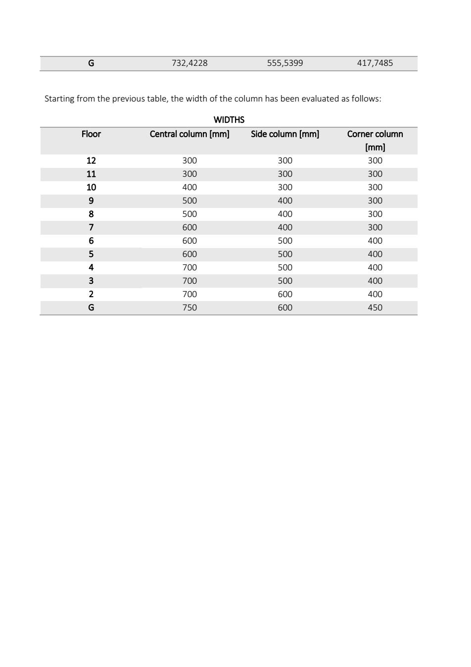
G 732,4228 555,5399 417,7485 Starting from the previous table, the width of the column has been evaluated as follows: WIDTHS Floor Central column [mm] Side column [mm] Corner column [mm] 12 300 300 300 11 300 300 300 10 400 300 300 9 500 400 300 8 500 400 300 7 600 400 300 6 600 500 400 5 600 500 400 4 700 500 400 3 700 500 400 2 700 600 400 G 750 600 450
DESIGN VERIFICATION OF THE COLUMNS ACCORDING TO THE CHINESE CODE: (Table6.1.2inGB50011-2010) Types of structure Seismic fortification intensity 8 9 Height (m)s24 >24 524 >24 ≤24>24≤24 am Frames 4th 3rd 3rd 2nd 2nd 1st structure 3rd 2nd 1st 15t Height(m) ≤60>60≤242560>60≤242560>60≤242560 Frames 4th 3rd 4th 3rd 2nd 3rd 2nd 1st 2nd 1st structure 3rd 3rd 2nd 2nd Height(m) ≤80>80≤242580>80s242580>80≤242560 structure ath 3rd 4th 3rd 2nd 3rd 2nd 1st 2nd Axial compression ratio bh-E≤0,750,8)→for24clas N Limit of axial compression ratio of columns Table6.3.6inGB50011-2010) Seismic grade ofstructure Type of structure 1 2 3 4 Frame structures 0.650.710.750.8)0.850.9j0.9 Wall-frame,slab-column-wall framed- tube and tube in tube structures 0.750.850.90.9510.95 Frames supporting walls of a partial walls supported by frame structures 0.60.7 Ductility of columns will be reduced if axial compression ration increase Weights [N] Floor Centre Side Corner 12 559,9125322,1269 182,1488 11 1119,82564,2538 364,2975 10 1679,738966,3806 546,4463 9 2239,65 1288,508 728,595 2799,5631610,634 910,7438
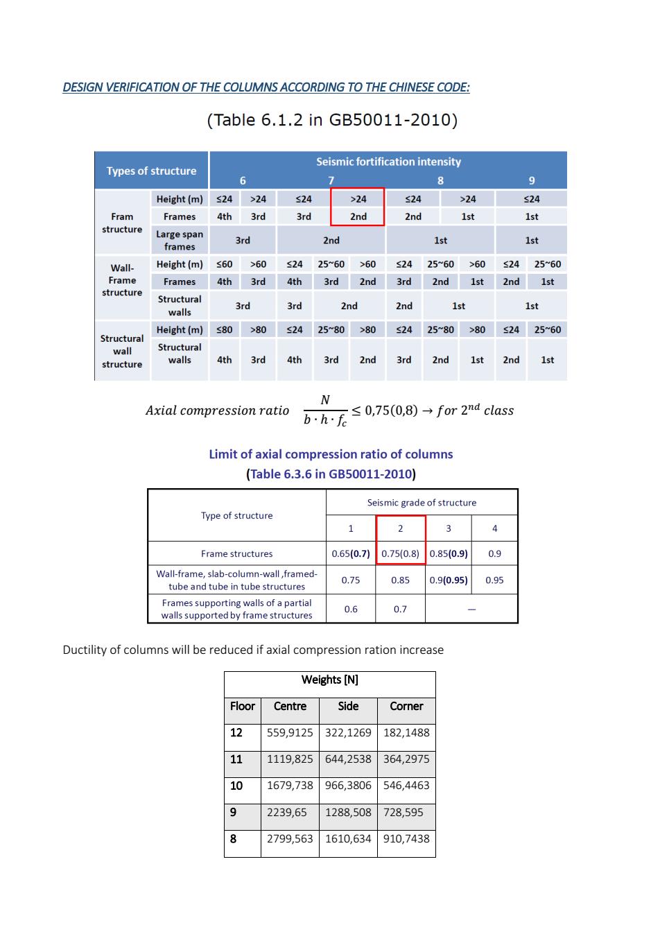
DESIGN VERIFICATION OF THE COLUMNS ACCORDING TO THE CHINESE CODE: Ductility of columns will be reduced if axial compression ration increase Weights [N] Floor Centre Side Corner 12 559,9125 322,1269 182,1488 11 1119,825 644,2538 364,2975 10 1679,738 966,3806 546,4463 9 2239,65 1288,508 728,595 8 2799,563 1610,634 910,7438

3359,4751932,7611092,893 3919,3882254,8881275,041 5 4479.3 2577,015 1457,19 5039,2132899,142 1639,339 5599.125 3221.269 1821,488 2 6159.038 3543,396 2003,636 6718,95 3865.5232185.785 Measurements [mm] Axial compression ratio Centre Side Corner b h b h b h Centre Side Corner 300 300 300 300 300 300 0,372530,2143230,12119 300 300 300 300 300 300 0.745060.4286450.24238 400 400 300 300 300 300 0,6286440,6429680,36357 500 500 400 400 300 300 0,5364430,4822260,48476 500 500 400 400 300 300 0,6705540,6027820,605951 600 600 400 400 300 300 0,5587950,7233390,727141 600 600 500 500 400 400 0,6519270.5400930,477186 600 600 500 500 400 400 0,745060.6172490,545356 700 700 500 500 400 400 0,6158150,6944050,613525 700 700 500 500 400 400 0,6842390,7715610,68169 700 700 600 600 400 400 0,7526630,5893870,749864 750 750 600 600 450 450 0,7152570,6429680,646347 As it possible to see from the table the verification of the axial compression ratio is satisfied for all the columns because each value is less than 0,75
7 3359,475 1932,761 1092,893 6 3919,388 2254,888 1275,041 5 4479,3 2577,015 1457,19 4 5039,213 2899,142 1639,339 3 5599,125 3221,269 1821,488 2 6159,038 3543,396 2003,636 1 6718,95 3865,523 2185,785 Measurements [mm] Axial compression ratio Centre Side Corner b h b h b h Centre Side Corner 300 300 300 300 300 300 0,37253 0,214323 0,12119 300 300 300 300 300 300 0,74506 0,428645 0,24238 400 400 300 300 300 300 0,628644 0,642968 0,36357 500 500 400 400 300 300 0,536443 0,482226 0,48476 500 500 400 400 300 300 0,670554 0,602782 0,605951 600 600 400 400 300 300 0,558795 0,723339 0,727141 600 600 500 500 400 400 0,651927 0,540093 0,477186 600 600 500 500 400 400 0,74506 0,617249 0,545356 700 700 500 500 400 400 0,615815 0,694405 0,613525 700 700 500 500 400 400 0,684239 0,771561 0,681694 700 700 600 600 400 400 0,752663 0,589387 0,749864 750 750 600 600 450 450 0,715257 0,642968 0,646347 As it possible to see from the table the verification of the axial compression ratio is satisfied for all the columns because each value is less than 0,75