
Contents Chapter 6 Dual System rwa . 6.1 Dual Structure Architectural Definition: · Materials: 5Sagc5aamwa Load-Carrying Characteristics of Dual sructure The walls provide most stifiness of lateral resistance are set in the centre of the st Erame-wall has tvn lines of 本课件版权归作者所有,仅供个人学习使用,请勿转载。1
1 Chapter 6 Dual System Xiong Haibei, Tongji University, 2015 Contents 6.1 Frame-Wall Structure 6.2 Simplified Calculation 6.3 Cooperation between Frame and Shear Wall 6.4 Design & Construction of Frame-Wall 6.5 Design & Construction of Slab-Column-Wall 6.6 Frame-Supproting Stories of Structure * 6.1 Dual Structure Definition: The system contains both frame and wall as lateral resistant system which bearing the lateral and vertical loads. Materials: Reinforced concrete frame-wall Steel-frame-RC-wall Architectural Characteristics of Frame-Wall Raising the height of structures ; Flexible space division; Used in shopping mall, office building, residential building and etc. Load-Carrying Characteristics of Dual structure The walls provide most stiffness of lateral resistance; When the walls are set in the centre of the structure, they provide high shearing stiffness only, and the columns of the frame provide high flexural rigidity; When the walls are set around the structure, they provide not only high shearing stiffness, but also great flexural and torsion rigidity; Frame-wall has two lines of anti-earthquake. Classification and Design Requirement Frame Overturning moment Load-carrying characteristic s Requireme nt of Height Requiremen t of Drift Seismic grading of shear wall Seismic grading of Frame 80% Close to frame Frame Frame-wall Frame-wall Frame 本课件版权归作者所有,仅供个人学习使用,请勿转载
Requirement of Height of Dual Structure Limit of Height-to-Width Ratio of Dual structure Frame-Wall: 6 de 0080m0.20.3 Slab.Column.Wall: 170m Limit of Displacement for Dual structure Arrangement of Structural Wall Qu时 ties of wall Limit values of displacement: imit vaue of icsy0 mit value of es-asy100 Plane Lavout of Structure Wall Vertical Layout of Structure Wall ·m rwalshedbeerrgsdcorinuouyiembotg ·1yomaehneogeydooheoodode sshoud be ined up in the same place.Wen cea.Thea国is of well 本课件版权归作者所有,仅供个人学习使用,请勿转载。2
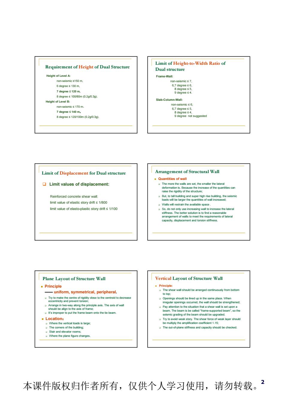
2 Requirement of Height of Dual Structure Height of Level A: non-seismic ≤150 m, 6 degree ≤ 130 m, 7 degree ≤ 120 m, 8 degree ≤ 100/80m (0.2g/0.3g). Height of Level B: non-seismic ≤ 170 m, 7 degree ≤ 140 m, 8 degree ≤ 120/100m (0.2g/0.3g). Limit of Height-to-Width Ratio of Dual structure Frame-Wall: non-seismic ≤ 7, 6,7 degree ≤ 6, 8 degree ≤ 5, 9 degree ≤ 4. Slab-Column-Wall: non-seismic ≤ 6, 6,7 degree ≤ 5, 8 degree ≤ 4, 9 degree not suggested Limit of Displacement for Dual structure Limit values of displacement: Reinforced concrete shear wall: limit value of elastic story drift ≤ 1/800 limit value of elasto-plastic story drift ≤ 1/100 Arrangement of Structural Wall Quantities of wall The more the walls are set, the smaller the lateral deformation is. Because the increase of the quantities can raise the rigidity of the structure; But, to tall building and super high rise building, the seismic loads will be larger the quantities of wall increased; Walls will restrain the available space . So, do not only use increasing wall to increase the lateral stiffness. The better solution is to find a reasonable arrangement of walls to meet the requirements of lateral capacity, displacement and torsion stiffness. Plane Layout of Structure Wall Principle —— uniform, symmetrical, peripheral. Try to make the centre of rigidity close to the centroid to decrease eccentricity and prevent torsion; Arrange in two-way along the principle axis. The axis of wall should be align to the axis of frame; It’s improper to put the frame beam onto the tie beam. Location: Where the vertical loads is large; The corners of the building; Stair and elevator rooms; Where the plane figure changes. Vertical Layout of Structure Wall Principle: The shear wall should be arranged continuously from bottom to top; Openings should be lined up in the same place. When irregular openings occurred, the wall should be strengthened; Pay attention to the situation that a shear wall is set upon a beam. The beam is be called “frame-supported beam”, so the seismic grading of the beam should be upgraded. Try to avoid weak story. The shear force of weak layer should be multiply the amplification coefficient 1.15; The out-of-plane stiffness and capacity should be checked. 本课件版权归作者所有,仅供个人学习使用,请勿转载
Arrangement of Structural Wall 6.2 Simplified Calculation of F-W 。Attention to The temperature stress elfect: aPlane torsion aThe contribution of in-plane stiffiness of slabs 出 6.2 Simplified Calculation of Frame-Wall 6.2 Simplified Cakulation of Frame-Wall .Assumption: Simplified method The in-plane stiffne of slab is infinite great: 6.2 Simplified Calculation of Frame-Wall 6.2 Simplified Calculation of Frame-Wall entativet .All frame. 。All shear-wall 本课件版权归作者所有,仅供个人学习使用,请勿转载。3
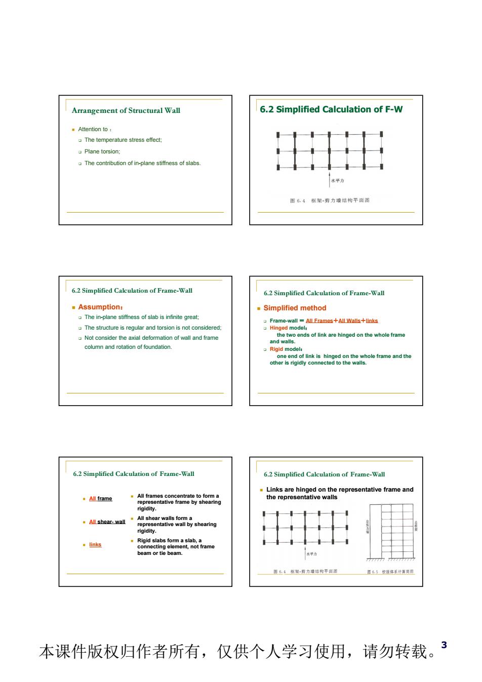
3 Arrangement of Structural Wall Attention to : The temperature stress effect; Plane torsion; The contribution of in-plane stiffness of slabs. 6.2 Simplified Calculation of F-W 6.2 Simplified Calculation of Frame-Wall Assumption: The in-plane stiffness of slab is infinite great; The structure is regular and torsion is not considered; Not consider the axial deformation of wall and frame column and rotation of foundation. 6.2 Simplified Calculation of Frame-Wall Simplified method Frame-wall = All Frames+All Walls+links Hinged model: the two ends of link are hinged on the whole frame and walls. Rigid model: one end of link is hinged on the whole frame and the other is rigidly connected to the walls. All frame All shear- wall links All frames concentrate to form a representative frame by shearing rigidity. All shear walls form a representative wall by shearing rigidity. Rigid slabs form a slab, a connecting element, not frame beam or tie beam. 6.2 Simplified Calculation of Frame-Wall Links are hinged on the representative frame and the representative walls 6.2 Simplified Calculation of Frame-Wall 本课件版权归作者所有,仅供个人学习使用,请勿转载
Simplified Calculation of Hinged Model Simplified Calculation of Rigid Model d on the whele 图6?赠提体系计年阅四 Simpified Rigid Model · -P-P main 本课件版权归作者所有,仅供个人学习使用,请勿转载。4
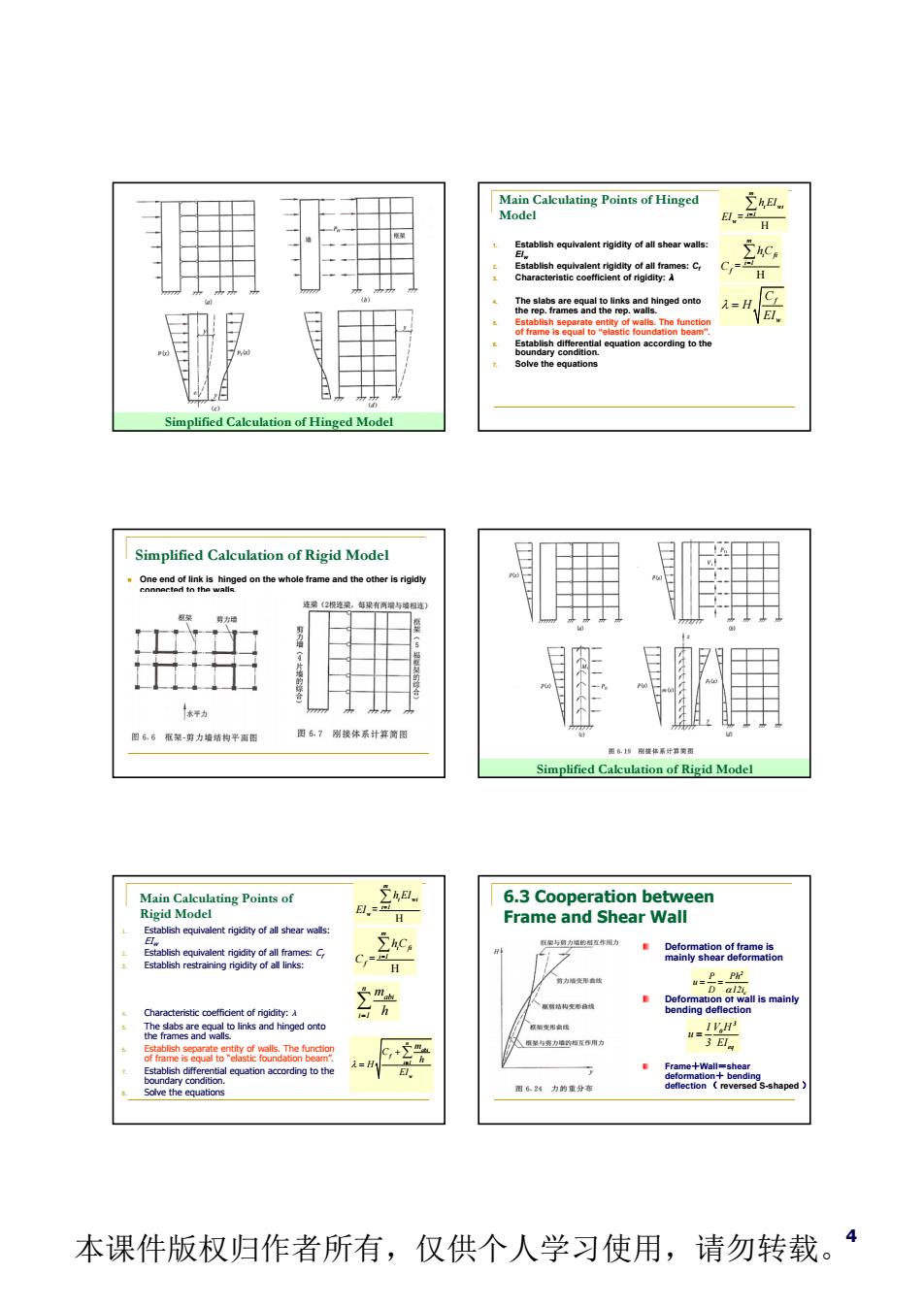
4 Simplified Calculation of Hinged Model Main Calculating Points of Hinged Model 1. Establish equivalent rigidity of all shear walls: EIw 2. Establish equivalent rigidity of all frames: Cf 3. Characteristic coefficient of rigidity: 4. The slabs are equal to links and hinged onto the rep. frames and the rep. walls. 5. Establish separate entity of walls. The function of frame is equal to “elastic foundation beam”. 6. Establish differential equation according to the boundary condition. 7. Solve the equations H m i fi i 1 f hC C = H m i wi i 1 w h EI EI = f w C H EI Simplified Calculation of Rigid Model One end of link is hinged on the whole frame and the other is rigidly connected to the walls. Simplified Calculation of Rigid Model Main Calculating Points of Rigid Model H m i fi i 1 f hC C = H m i wi i 1 w h EI EI = n abi f i 1 w m C h H EI n abi i 1 m h 1. Establish equivalent rigidity of all shear walls: EIw 2. Establish equivalent rigidity of all frames: Cf 3. Establish restraining rigidity of all links: 4. Characteristic coefficient of rigidity: 5. The slabs are equal to links and hinged onto the frames and walls. 6. Establish separate entity of walls. The function of frame is equal to “elastic foundation beam”. 7. Establish differential equation according to the boundary condition. 8. Solve the equations 6.3 Cooperation between Frame and Shear Wall Deformation of frame is mainly shear deformation Deformation of wall is mainly bending deflection Frame+Wall=shear deformation+ bending deflection ( reversed S-shaped ) 3 0 eq 1 V H u 3 EI 2 c P Ph u D 12i 本课件版权归作者所有,仅供个人学习使用,请勿转载

Cooperation between Frame and Shea Seismic grading for reinforced concrete buildings 6.4 Design&Construction of F-W (Table61.2inGB5001-2010) 1.Frame-Wa Structures 一k6 ing nt,the can be r noment be continued (Table6.1.2nG850011-2010) 6.4 Design Construction of F-W V20.2。 V≥1V 本课件版权归作者所有,仅供个人学习使用,请勿转载。5
5 Cooperation between Frame and Shear Cooperation between Frame and Wall n abi f i 1 w m C h H E I 6.4 Design & Construction of F-W 1. Frame-Wall Structures Under the seismic action of basic vibration mode, if frame’s overturning moment is bigger than 50% of the total overturning moment, the seismic grading of frame is determined on the basis of frame structure and the maximum height can be raised properly, interpolated according to the percentage of frame’s overturning moment. In otherwise, it can use dual system to grade frame and wall. Seismic grading for reinforced concrete buildings (Table 6.1.2 in GB50011-2010) Types of structure Seismic fortification intensity 67 8 9 Fram structure Height (m) ≤24 >24 ≤24 >24 ≤24 >24 ≤24 Frames 4th 3rd 3rd 2nd 2nd 1st 1st Large span frames 3rd 2nd 1st 1st Wall‐ Frame structure Height (m) ≤60 >60 ≤24 25~60 >60 ≤24 25~60 >60 ≤24 25~60 Frames 4th 3rd 4th 3rd 2nd 3rd 2nd 1st 2nd 1st Structural walls 3rd 3rd 2nd 2nd 1st 1st Structural wall structure Height (m) ≤80 >80 ≤24 25~80 >80 ≤24 25~80 >80 ≤24 25~60 Structural walls 4th 3rd 4th 3rd 2nd 3rd 2nd 1st 2nd 1st be continued Types of structure Seismic fortification intensity 6 7 89 Frame ‐ supported wall structure Height (m) ≤80 >80 ≤24 25~ 80 >80 ≤24 25~ 80 Struc‐ tural walls General 4th 3rd 4th 3rd 2nd 3rd 2nd Streng‐ thening 3rd 2nd 3rd 2nd 1stI 2nd 1st Frames that supporting walls 2nd 2nd 1st 1st Framed‐tube structure Frame 3rd 2nd 1st 1st Tube 2nd 2nd 1st 1st Tube in tube structure Exterior tube 3rd 2nd 1st 1st Interior tube 3rd 2nd 1st 1st Slab‐column‐ wall structure Height (m) ≤35 >35 ≤35 >35 ≤35 >35 Columns 3rd 2nd 2nd 2nd 1st Walls 2nd 2nd 2nd 1st 2nd 1st (Table 6.1.2 in GB50011-2010) Shear force adjusting frame’s shear force of each story should satisfy Vf,max maximum shear force of frame of each story The frame columns and beams should designed according this adjusted value. ,max . . 0 f V 0 2V V 1 5V 6.4 Design & Construction of F-W 本课件版权归作者所有,仅供个人学习使用,请勿转载
6.4 Design Construction of F-W 6.4 Design Construction of F-W Non-seismic design:% 0025%1 6.5 Des mn-Walltio em Wall System ctio uirements for slab-column aeou 6.6 本课件版权归作者所有,仅供个人学习使用,请勿转载。6
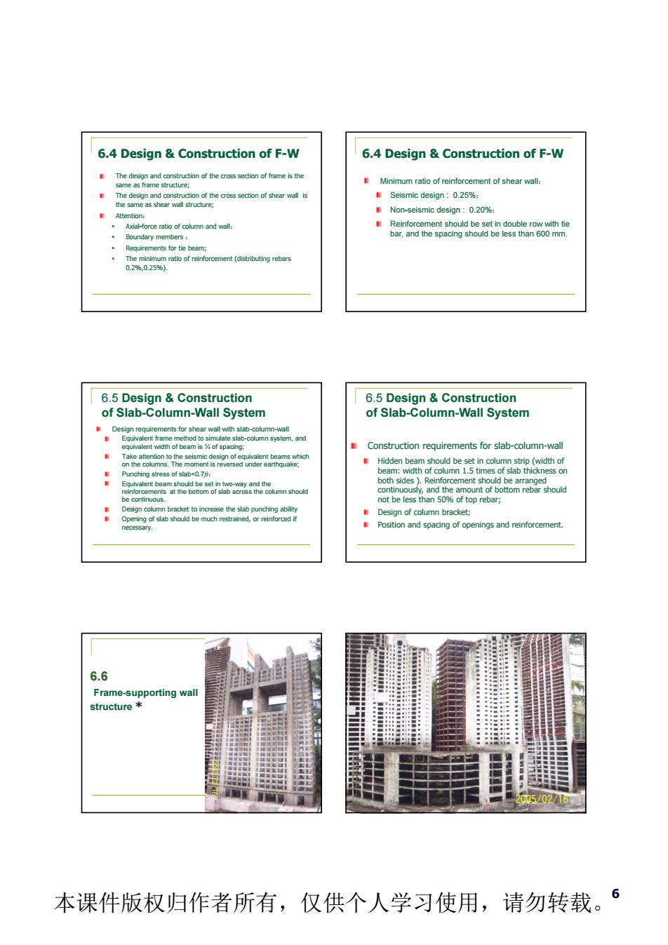
6 The design and construction of the cross section of frame is the same as frame structure; The design and construction of the cross section of shear wall is the same as shear wall structure; Attention: Axial-force ratio of column and wall; Boundary members ; Requirements for tie beam; The minimum ratio of reinforcement (distributing rebars 0.2%,0.25%). 6.4 Design & Construction of F-W Minimum ratio of reinforcement of shear wall: Seismic design : 0.25%; Non-seismic design : 0.20%; Reinforcement should be set in double row with tie bar, and the spacing should be less than 600 mm. 6.4 Design & Construction of F-W 6.5 Design & Construction of Slab-Column-Wall System Design requirements for shear wall with slab-column-wall Equivalent frame method to simulate slab-column system, and equivalent width of beam is ¼ of spacing; Take attention to the seismic design of equivalent beams which on the columns. The moment is reversed under earthquake; Punching stress of slab<0.7ft; Equivalent beam should be set in two-way and the reinforcements at the bottom of slab across the column should be continuous. Design column bracket to increase the slab punching ability Opening of slab should be much restrained, or reinforced if necessary. Construction requirements for slab-column-wall Hidden beam should be set in column strip (width of beam: width of column 1.5 times of slab thickness on both sides ). Reinforcement should be arranged continuously, and the amount of bottom rebar should not be less than 50% of top rebar; Design of column bracket; Position and spacing of openings and reinforcement. 6.5 Design & Construction of Slab-Column-Wall System 6.6 Frame-supporting wall structure * 本课件版权归作者所有,仅供个人学习使用,请勿转载
Characteristics of Difficult Points of Frame-Supporting Wall Structure Frame-Supporting Wall Structure 器 ‘7 本课件版权归作者所有,仅供个人学习使用,请勿转载。7
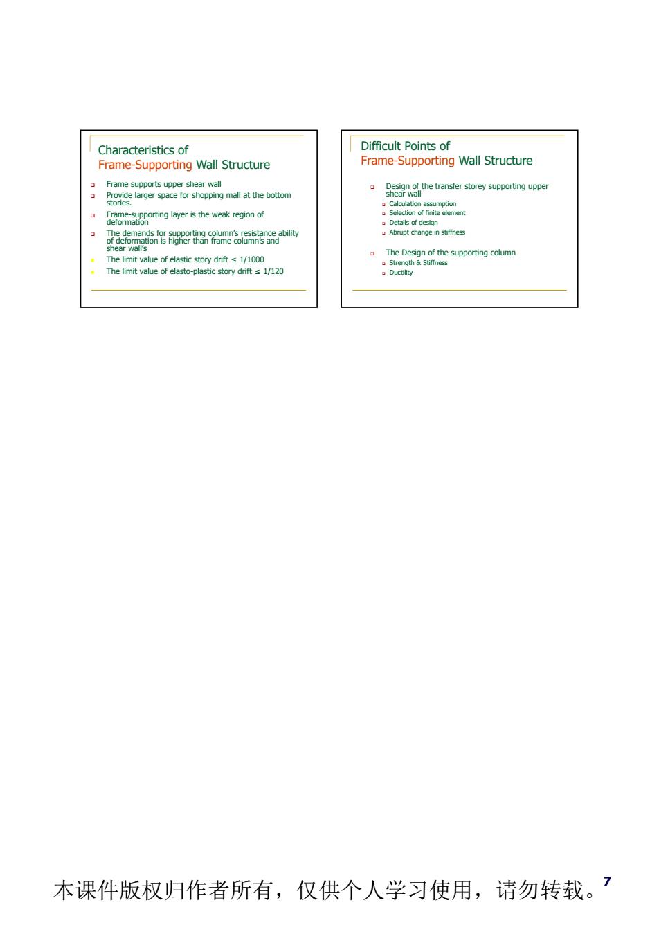
7 Characteristics of Frame-Supporting Wall Structure Frame supports upper shear wall Provide larger space for shopping mall at the bottom stories. Frame-supporting layer is the weak region of deformation The demands for supporting column’s resistance ability of deformation is higher than frame column’s and shear wall’s The limit value of elastic story drift 1/1000 The limit value of elasto-plastic story drift 1/120 Difficult Points of Frame-Supporting Wall Structure Design of the transfer storey supporting upper shear wall Calculation assumption Selection of finite element Details of design Abrupt change in stiffness The Design of the supporting column Strength & Stiffness Ductility 本课件版权归作者所有,仅供个人学习使用,请勿转载