General earthquake design in Europe by Eurocode SFS-EN 1998-1 Tall Building Structures report 3 Kari Parila 1570053
General earthquake design in Europe by Eurocode SFS-EN 1998-1 Tall Building Structures report 3 Kari Parila 1570053
In seismic regions the aspect of seismic hazard shall be taken into account.Finland is located to very low seismic risk area,so this report will introduce general principles of earthquake design by SFS-EN 1998-1.The guiding principles which should be taken into account when designing an earthquake resistant building are stated in Eurocode as following: Structural simplicity Uniformity,symmetry and redundancy Bi-directional resistance and stiffness Diaphragmatic behavior at story level Adequate foundation Buildings are categorized into being regular or non-regular and these buildings are still categorized to important classes from 1 to 4 as shown in table below.These important classes correspond roughly with SFS-EN 1990-1 Annex B consequence classes CC1,CC2 and CC3 which are defined by economica and human safety risks.In Finland only building consequence classes are used because according to SFS-EN 1998-1 earthquake design doesn't have to be done at very low earthquake risk areas. Depending on the importance class,different kinds of safety factors(y)are used when seismic effects are calculated. Importance Buildings class I Buildings of minor importance for public safety.e.g.agricultural buildings.etc. Ordinary buildings.not belonging in the other categories. 分 Buildings whose seismic resistance is of importance in view of the consequences associated with a collapse.e.g.schools.assembly halls. cultural institutions ete. N Buildings whose integrity during earthquakes is of vital importance for civil protection.e.g.hospitals.fire stations.power plants.ete. Figure1.SFS-EN1998-1Table4.3 In order to define seismic effects to the building,it is necessary to inspect ground motions.SFS-EN 1998-13.1-3.2 introduces procedure to calculate effects of ground motion.Ground types are divided to ordinary classes A,B,C,D and E and to special classes S1 and S2.Class A is the hardest ground type and class E is the softest.Special ground types$1 and 52 needs special studies of earthquake actions and possibility to soil failure has to be taken into account.More specific information of ground types can be found from SFS-EN 1998-1 Table 3.1
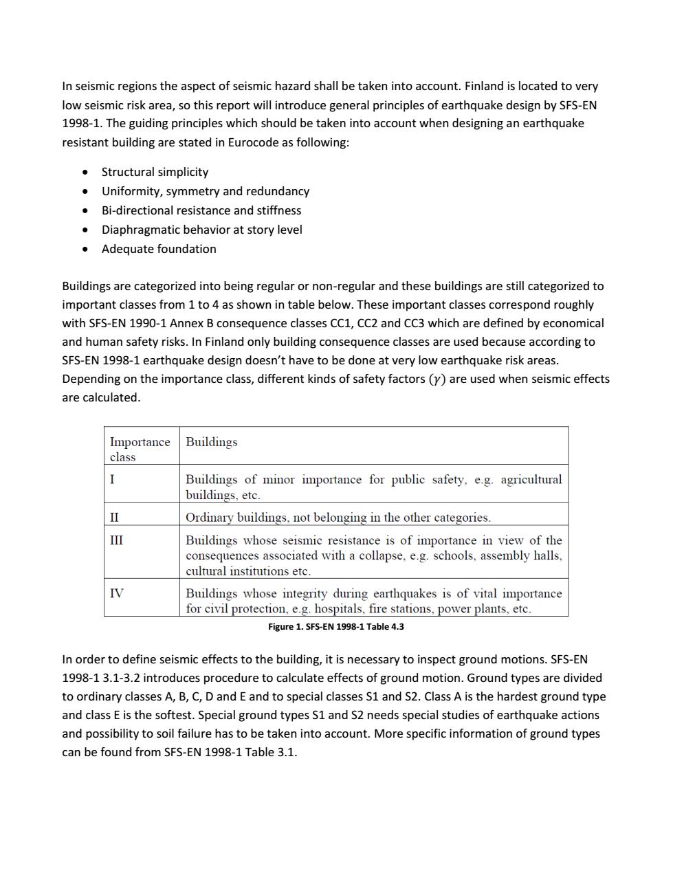
In seismic regions the aspect of seismic hazard shall be taken into account. Finland is located to very low seismic risk area, so this report will introduce general principles of earthquake design by SFS-EN 1998-1. The guiding principles which should be taken into account when designing an earthquake resistant building are stated in Eurocode as following: Structural simplicity Uniformity, symmetry and redundancy Bi-directional resistance and stiffness Diaphragmatic behavior at story level Adequate foundation Buildings are categorized into being regular or non-regular and these buildings are still categorized to important classes from 1 to 4 as shown in table below. These important classes correspond roughly with SFS-EN 1990-1 Annex B consequence classes CC1, CC2 and CC3 which are defined by economical and human safety risks. In Finland only building consequence classes are used because according to SFS-EN 1998-1 earthquake design doesn’t have to be done at very low earthquake risk areas. Depending on the importance class, different kinds of safety factors are used when seismic effects are calculated. Figure 1. SFS-EN 1998-1 Table 4.3 In order to define seismic effects to the building, it is necessary to inspect ground motions. SFS-EN 1998-1 3.1-3.2 introduces procedure to calculate effects of ground motion. Ground types are divided to ordinary classes A, B, C, D and E and to special classes S1 and S2. Class A is the hardest ground type and class E is the softest. Special ground types S1 and S2 needs special studies of earthquake actions and possibility to soil failure has to be taken into account. More specific information of ground types can be found from SFS-EN 1998-1 Table 3.1
The earthquake motion at a given point on the surface is represented by an elastic ground acceleration response spectrum which is called an elastic response spectrum.The horizontal seismic action is described by two orthogonal components and vertical by one component.For the three components of the seismic actions,one or more alternative shapes of response spectra may be adopted.Upper figure(below)is general form of the elastic response spectrum. r( T Figure 2.Type1 response spectra Figure 3.Type 2 response spectra If geology is not accounted to the design process then it is suggested to use type 1 and type 2 response spectrums.If surface-wave magnitude is not greater than 5.5 then it is recommended to use type 2 response spectrum.SFS-EN 1998-1 Table 3.2 and Table 3.1 represent the values used for type 1 and type 2 response spectrums.Response spectrum data is needed to calculate seismic effects to the building. Seismic effects are calculated on the basis of the linear-elastic behavior of the structure.There are two main(1 and 2)and two alternative(3 and 4)calculation procedures to calculate seismic effects. Selection of the seismic effects calculation procedure depends on regularity of the structure and table below(Figure 4)can be used as a help.More specific information about regularity can be found from SFS-EN 1998-14.2.3.Calculation methods as listed as following:
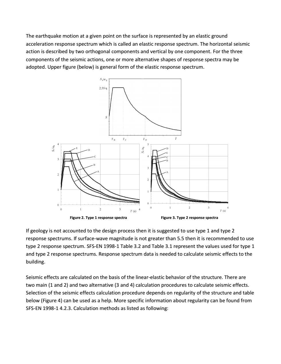
The earthquake motion at a given point on the surface is represented by an elastic ground acceleration response spectrum which is called an elastic response spectrum. The horizontal seismic action is described by two orthogonal components and vertical by one component. For the three components of the seismic actions, one or more alternative shapes of response spectra may be adopted. Upper figure (below) is general form of the elastic response spectrum. Figure 2. Type 1 response spectra Figure 3. Type 2 response spectra If geology is not accounted to the design process then it is suggested to use type 1 and type 2 response spectrums. If surface-wave magnitude is not greater than 5.5 then it is recommended to use type 2 response spectrum. SFS-EN 1998-1 Table 3.2 and Table 3.1 represent the values used for type 1 and type 2 response spectrums. Response spectrum data is needed to calculate seismic effects to the building. Seismic effects are calculated on the basis of the linear-elastic behavior of the structure. There are two main (1 and 2) and two alternative (3 and 4) calculation procedures to calculate seismic effects. Selection of the seismic effects calculation procedure depends on regularity of the structure and table below (Figure 4) can be used as a help. More specific information about regularity can be found from SFS-EN 1998-1 4.2.3. Calculation methods as listed as following:
1.Lateral force method of analysis-not usable for all types of structures 2.Modal response spectrum analysis-can be used to all types of structures 3.Non-linear static(pushover)analysis 4.Non-linear time-history(dynamic)analysis Regularity Allowed Simplificatio Behaviour factor Plan Elevation Mode Linear-elastic Analysis (for linear analysis Yes Yes Planar Lateral force" Reference value Yes Plana Modal Yes Lateral force Reterence valu NoNo Spatial Modal Decreased value Figure 4.SFS-EN 1998-1Table 4.1 Lateral force method(SFS-EN 1998-1 4.3.3.2)can be used if building satisfies regularity criteria and 4T. fundamental vibration restrictions in both horizontal directions are Ti -Where Te is obtained from response spectrum.The seismic base shear force for each horizontal direction in which building is analysed,can be obtained from equationF=Sm Structural engineer can choose if he calculates fundamental period with simplified method or with structural dynamics.SFS-EN 1998-1 represents simplified method.Distribution of seismic load is made with following equation(if fundamental period is approximated by horizontal displacements,then s in the equation is replaced with z=height of the masses): where F is the horizontal force acting on storey i: F is the seismic base shear in accordance with expression (4.5): ss are the displacemeuts of mass nthe mode shape the storey masses computed in accordancs with 3.2.4(2). Torsional effects are taken to account by accidental torsional effects which is caused by eccentricity or torsional effects can be calculated by more exact method.Accidental torsional effects are calculated by multiplying the action effects with 6=l0.62 4.12)
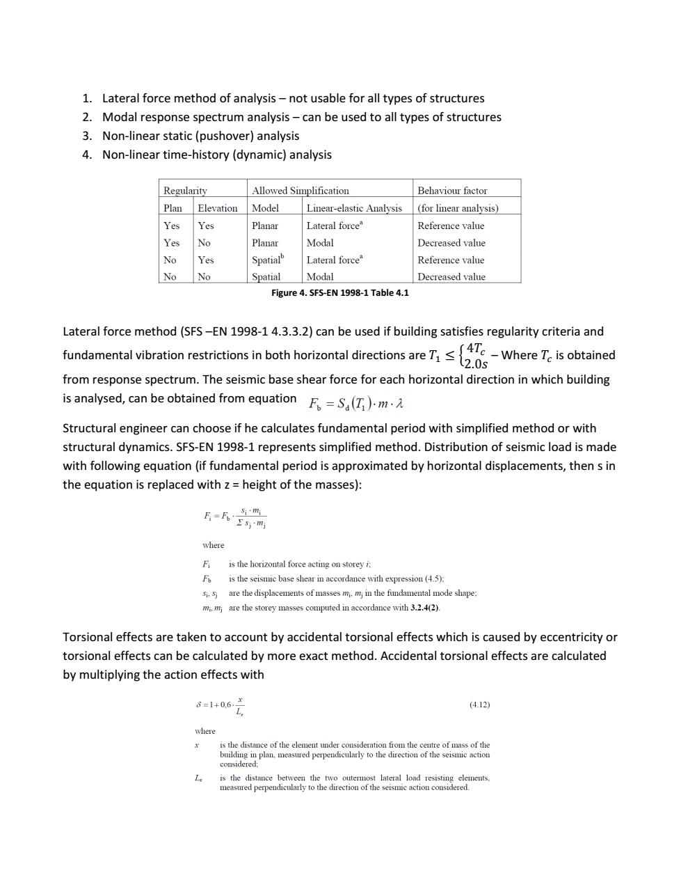
1. Lateral force method of analysis – not usable for all types of structures 2. Modal response spectrum analysis – can be used to all types of structures 3. Non-linear static (pushover) analysis 4. Non-linear time-history (dynamic) analysis Figure 4. SFS-EN 1998-1 Table 4.1 Lateral force method (SFS –EN 1998-1 4.3.3.2) can be used if building satisfies regularity criteria and fundamental vibration restrictions in both horizontal directions are { – Where is obtained from response spectrum. The seismic base shear force for each horizontal direction in which building is analysed, can be obtained from equation Structural engineer can choose if he calculates fundamental period with simplified method or with structural dynamics. SFS-EN 1998-1 represents simplified method. Distribution of seismic load is made with following equation (if fundamental period is approximated by horizontal displacements, then s in the equation is replaced with z = height of the masses): Torsional effects are taken to account by accidental torsional effects which is caused by eccentricity or torsional effects can be calculated by more exact method. Accidental torsional effects are calculated by multiplying the action effects with
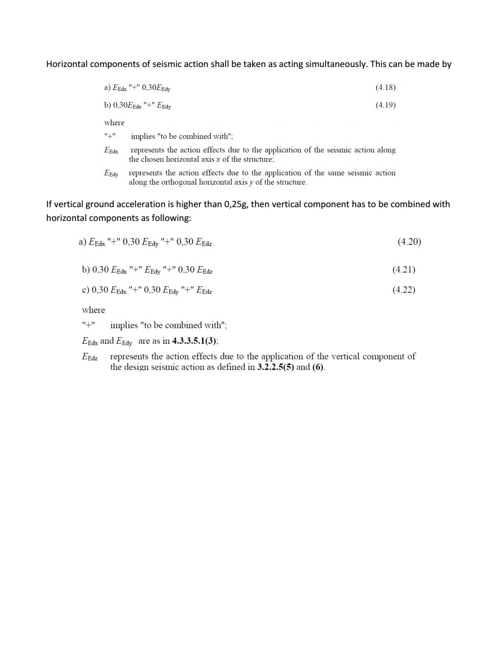
Horizontal components of seismic action shall be taken as acting simultaneously.This can be made by a)EEh"+"0.,30EE (4.18) b)0,30EE"+"EE动 (4.19) where implies "to be combined with"; hehosaihoiSnlarroteontmancaiaofthecimieacioualoag ats the ac effects due to the a of the same seismic action If vertical ground acceleration is higher than 0,25g,then vertical component has to be combined with horizontal components as following: a)EE"+"0.30EE"+"0,30EE (4.20) b)0,30EEk"+"E"+"0.30EEd (4.21) c)0.30EE"+"0,30EE"+"EE 4.22) where "implies"to be combined with" Egds and Egdy are as in 4.3.3.5.1(3): EEdz represents the action effects due to the application of the vertical component of the design seismic action as defined in 3.2.2.5(5)and (6)
Horizontal components of seismic action shall be taken as acting simultaneously. This can be made by If vertical ground acceleration is higher than 0,25g, then vertical component has to be combined with horizontal components as following: