
Understand the diffraction peak broadening in XRD Leyun Wang School of Materials Science and Engineering,SJTU leyunwang@sjtu.edu.cn
Understand the diffraction peak broadening in XRD Leyun Wang School of Materials Science and Engineering, SJTU leyunwang@sjtu.edu.cn

Definition of peak broadening Full Width at Half Maximum (FWHM) the width of the diffraction peak, FWHM in radians,at a height half-way between background and the peak maximum ·Integral Breadth the total area under the peak divided by the peak height 46.746.846.947.047.147.247.347.447.547.647.747.847.9 20(deg.) the width of a rectangle having the same area and the same height as the peak requires very careful evaluation of the tails of the peak and the (n'e) background 48745846947047.147247347447547847.7478479 20(deg-)
46.7 46.8 46.9 47.0 47.1 47.2 47.3 47.4 47.5 47.6 47.7 47.8 47.9 2 (deg.) Intensity (a.u.) Definition of peak broadening • Full Width at Half Maximum (FWHM) – the width of the diffraction peak, in radians, at a height half-way between background and the peak maximum • Integral Breadth – the total area under the peak divided by the peak height – the width of a rectangle having the same area and the same height as the peak – requires very careful evaluation of the tails of the peak and the background 46.746.846.947.047.147.2 47.347.447.547.647.747.847.9 2 (deg.) Intensity (a.u.) FWHM

Many factors may contribute to the observed peak broadening Instrumental Peak Profile ·Crystallite Size ·Microstrain Non-uniform Lattice Distortions Faulting Dislocations Antiphase Domain Boundaries -Grain Surface Relaxation Solid Solution Inhomogeneity ·Temperature Factors The peak profile is a convolution of the profiles from all of these contributions
Many factors may contribute to the observed peak broadening • Instrumental Peak Profile • Crystallite Size • Microstrain – Non-uniform Lattice Distortions – Faulting – Dislocations – Antiphase Domain Boundaries – Grain Surface Relaxation • Solid Solution Inhomogeneity • Temperature Factors • The peak profile is a convolution of the profiles from all of these contributions
Instrument and Sample Contributions to the Peak Profile must be Deconvoluted In order to analyze crystallite size and microstrain in the specimen,we must deconvolute: -Instrumental Broadening FW(I) also referred to as the Instrumental Profile,Instrumental FWHM Curve,Instrumental Peak Profile Specimen Broadening FW(S) also referred to as the Sample Profile,Specimen Profile We must then separate the different contributions to specimen broadening Crystallite size and microstrain broadening of diffraction peaks
Instrument and Sample Contributions to the Peak Profile must be Deconvoluted
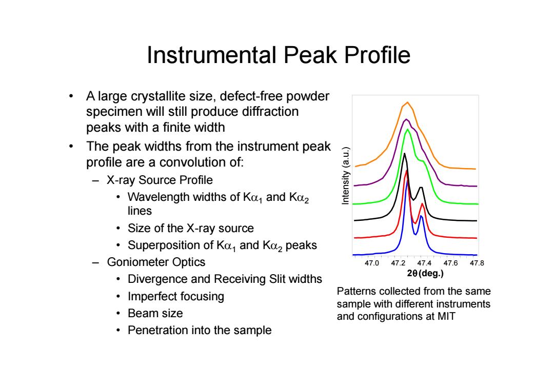
Instrumental Peak Profile A large crystallite size,defect-free powder specimen will still produce diffraction peaks with a finite width The peak widths from the instrument peak profile are a convolution of: X-ray Source Profile ('n'e)Au!suejul Wavelength widths of Ka and Ko2 lines Size of the X-ray source Superposition of Ka and Ka2 peaks Goniometer Optics 47.047.247.447.647.8 Divergence and Receiving Slit widths 2θ(deg.) ·Imperfect focusing Patterns collected from the same sample with different instruments ·Beam size and configurations at MIT Penetration into the sample
Instrumental Peak Profile • A large crystallite size, defect-free powder specimen will still produce diffraction peaks with a finite width • The peak widths from the instrument peak profile are a convolution of: – X-ray Source Profile • Wavelength widths of K 1 and K 2 lines • Size of the X-ray source • Superposition of K 1 and K 2 peaks – Goniometer Optics • Divergence and Receiving Slit widths • Imperfect focusing • Beam size • Penetration into the sample 47.0 47.2 47.4 47.6 47.8 2 (deg.) Intensity (a.u.) Patterns collected from the same sample with different instruments and configurations at MIT
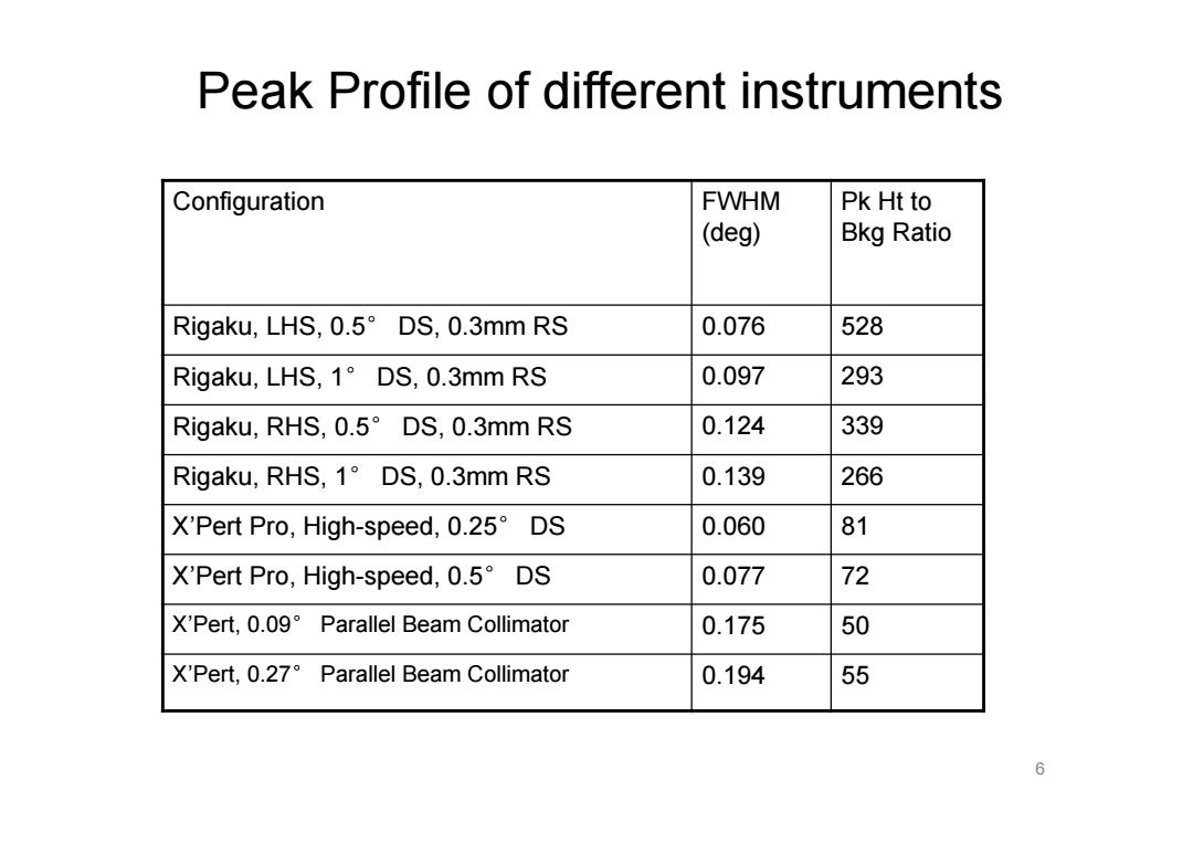
Peak Profile of different instruments Configuration FWHM Pk Ht to (deg) Bkg Ratio Rigaku,LHS,0.5 DS,0.3mm RS 0.076 528 Rigaku,LHS,1 DS,0.3mm RS 0.097 293 Rigaku,RHS,0.5DS,0.3mm RS 0.124 339 Rigaku,RHS,1 DS,0.3mm RS 0.139 266 X'Pert Pro,High-speed,0.25 DS 0.060 81 X'Pert Pro,High-speed,0.5 DS 0.077 72 X'Pert,0.09 Parallel Beam Collimator 0.175 50 X'Pert,0.27 Parallel Beam Collimator 0.194 55 6
6 Configuration FWHM (deg) Pk Ht to Bkg Ratio Rigaku, LHS, 0.5° DS, 0.3mm RS 0.076 528 Rigaku, LHS, 1° DS, 0.3mm RS 0.097 293 Rigaku, RHS, 0.5° DS, 0.3mm RS 0.124 339 Rigaku, RHS, 1° DS, 0.3mm RS 0.139 266 X’Pert Pro, High-speed, 0.25° DS 0.060 81 X’Pert Pro, High-speed, 0.5° DS 0.077 72 X’Pert, 0.09° Parallel Beam Collimator 0.175 50 X’Pert, 0.27° Parallel Beam Collimator 0.194 55 Peak Profile of different instruments
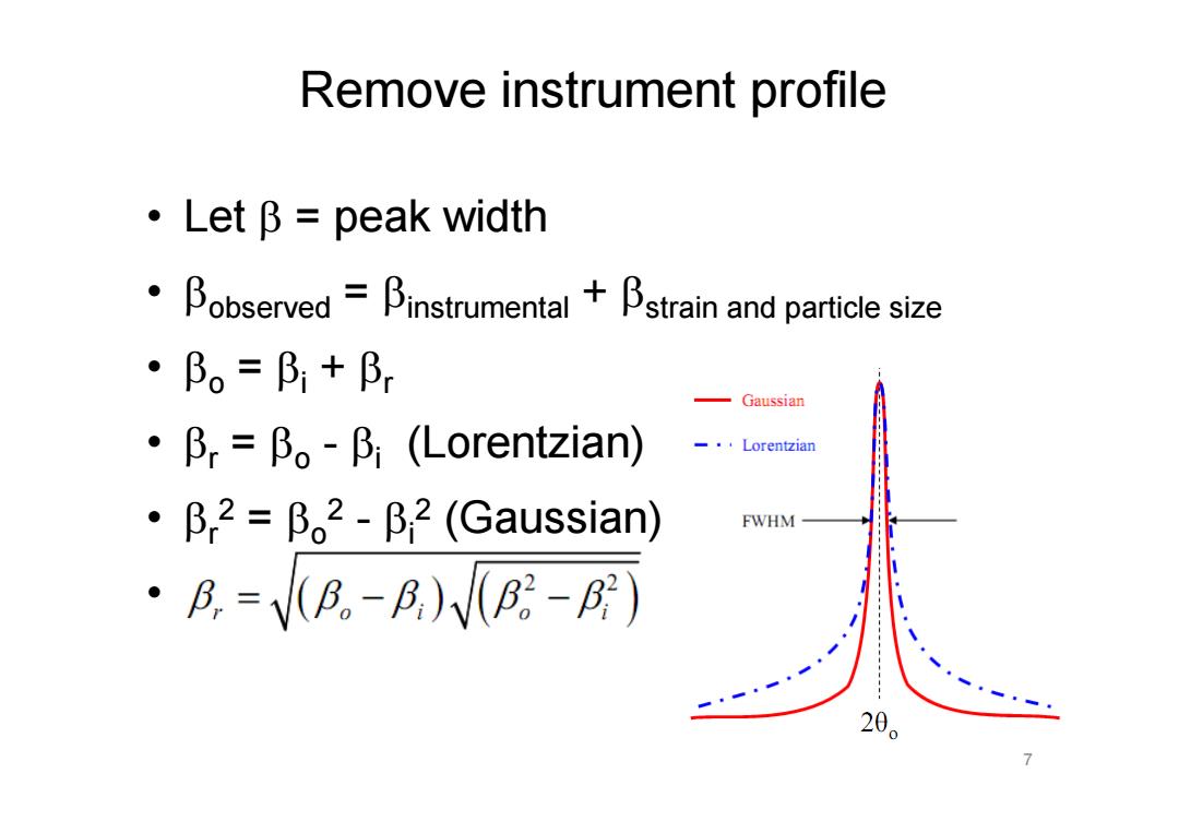
Remove instrument profile ·LetB=peak width Bobserved-Binstrumental +Bstrain and particle size ·Bo=B+Br Gaussian ·Pr=β。-β,(Lorentzian) Lorentzian ·β,2=β。2-β,2(Gaussian) FWHM ·A.=VB。-R)VB-B) 20
• Let = peak width • observed = instrumental + strain and particle size • o = i + r • r = o - i (Lorentzian) • r2 = o2 - i2 (Gaussian) • 7 Remove instrument profile

Crystallite Size Broadening K九 B(20)= - 0.94元 B(28)= Lcose L cos 0 The Scherrer Equation(1918) Peak Width due to crystallite size varies inversely with crystallite size L (or D) as the crystallite size gets smaller,the peak gets broader The peak width varies with 0 The crystallite size broadening is most pronounced at large 20
Crystallite Size Broadening • Peak Width due to crystallite size varies inversely with crystallite size L (or D) – as the crystallite size gets smaller, the peak gets broader • The peak width varies with – The crystallite size broadening is most pronounced at large 2 cos 2 L K B The Scherrer Equation (1918) cos 0.94 2 L B
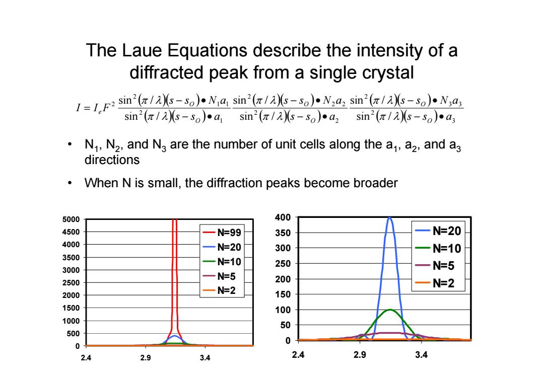
The Laue Equations describe the intensity of a diffracted peak from a single crystal 11sin(-so)Na sin(/s-s0)Nadz sin'(/As-so).N,a, sin2(π/)s-so)a1sin2(π/2-so)•a2sin2(π/2)s-so)a3 o N,,N2,and Na are the number of unit cells along the a,a2,and a3 directions When N is small,the diffraction peaks become broader 5000 400 4500 N=99 350 N=20 4000 N=20 300 N=10 3500 N=10 250 3000 N=5 N=5 2500 200 一N=2 N=2 2000 150 1500 100 1000 500 0 0 2.4 2.9 3.4 2.4 2.9 3.4
The Laue Equations describe the intensity of a diffracted peak from a single crystal • N1, N 2, and N 3 are the number of unit cells along the a1, a 2, and a 3 directions • When N is small, the diffraction peaks become broader 3 2 3 3 2 2 2 2 2 2 1 2 1 1 2 2 sin / sin / sin / sin / sin / sin / s s a s s N a s s a s s N a s s a s s N a I I F O O O O O O e 0 500 1000 1500 2000 2500 3000 3500 4000 4500 5000 2.4 2.9 3.4 N=99 N=20 N=10 N=5 N=2 0 50 100 150 200 250 300 350 400 2.4 2.9 3.4 N=20 N=10 N=5 N=2
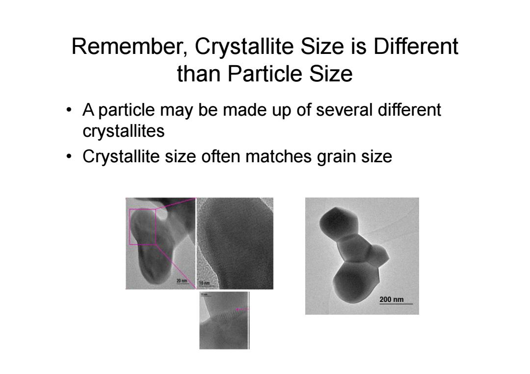
Remember,Crystallite Size is Different than Particle Size A particle may be made up of several different crystallites Crystallite size often matches grain size 200nm
Remember, Crystallite Size is Different than Particle Size • A particle may be made up of several different crystallites • Crystallite size often matches grain size