Image contrast in TEM and its application Lanting Zhang School of Materials Science and Engineering SJTU lantingzh@sjtu.edu.cn 1
Image contrast in TEM and its application Lanting Zhang School of Materials Science and Engineering, SJTU lantingzh@sjtu.edu.cn 1
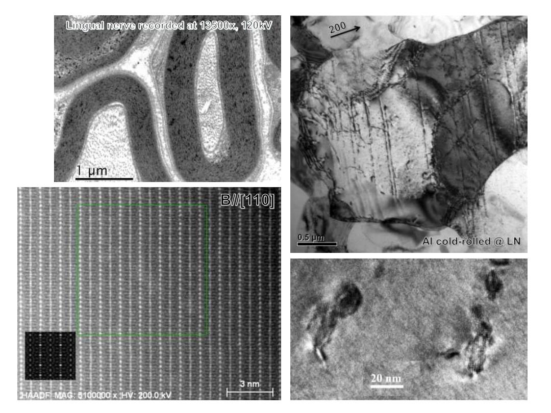
Lingual nerve recorded at 13500x.120kV 200 I um B110] 0,5pm Al cold-rolled LN 3nm 20 nm HHAADF MAG:5100000x HV:200.0KV
2
Why there is no colour in the pictures? Understanding the B&W contrast in image. 3
Why there is no colour in the pictures? 3

Nature of image contrast Mass-thickness contrast Annular dark field (ADF-STEM) HAADF,if 0in>50 mrad Amplitude contrast Diffraction contrast Kinematic theory and expression Phase contrast (HREM) Thin specimen 10 nm 4
Nature of image contrast • Mass-thickness contrast • Annular dark field (ADF-STEM) – HAADF, if in > 50 mrad • Diffraction contrast – Kinematic theory and expression • Phase contrast (HREM) – Thin specimen < 10 nm 4 Amplitude contrast
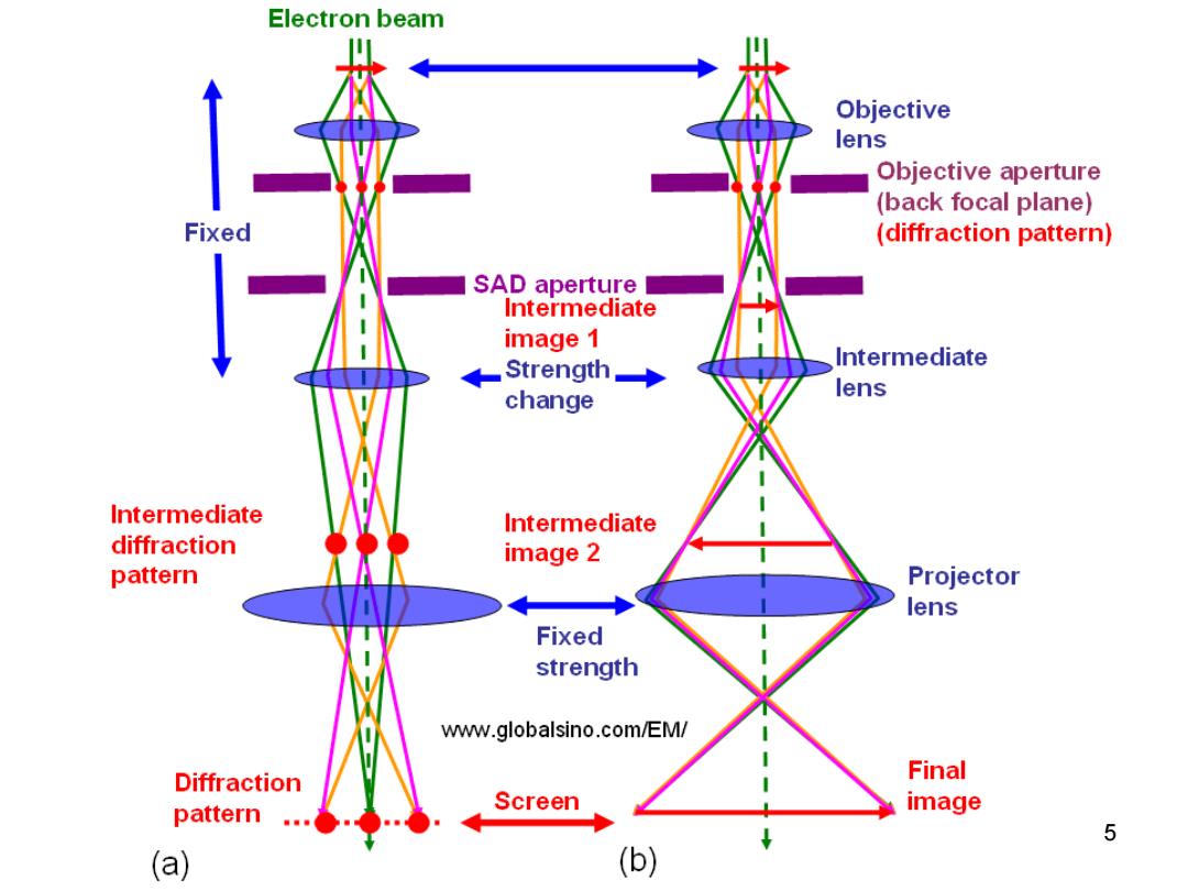
Electron beam Objective lens Objective aperture (back focal plane) Fixed (diffraction pattern) SAD aperture Intermediate image 1 Strength→ Intermediate change lens Intermediate Intermediate diffraction image 2 pattern Projector lens Fixed strength www.globalsino.com/EM/ Diffraction Final pattern Screen image 5 (a) (b)
5
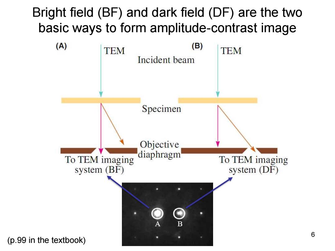
Bright field (BF)and dark field(DF)are the two basic ways to form amplitude-contrast image (A) TEM (B) TEM Incident beam Specimen Objective To TEM imaging diaphragm To TEM imaging system(BF) system (DF) 6 (p.99 in the textbook)
Bright field (BF) and dark field (DF) are the two basic ways to form amplitude-contrast image 6 (p.99 in the textbook)
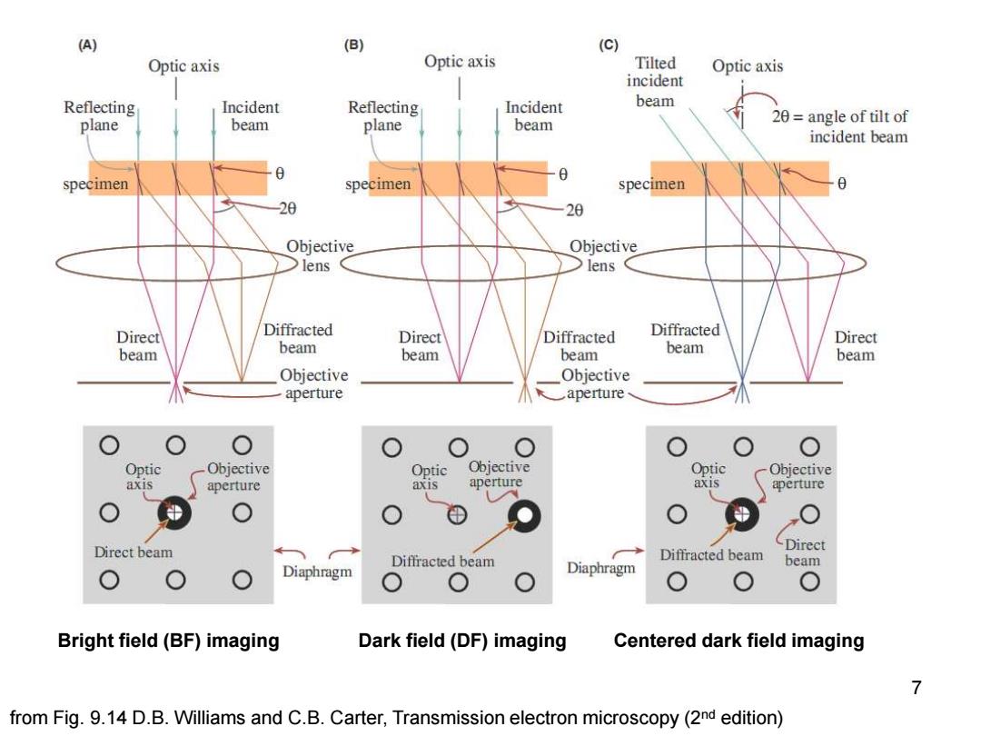
(A) (B) (C) Optic axis Optic axis Tilted Optic axis incident Reflecting Incident Reflecting Incident beam plane beam plane beam 20=angle of tilt of incident beam specimen specimen specimen 20 20 Objective Objective lens lens Direct Diffracted Direct Diffracted Diffracted Direct beam beam beam beam beam beam Objective Objective aperture aperture 0 Optic Objective Optic Objective Optic Objective axis aperture axis aperture axis aperture Direct beam Diffracted beam Diffracted beam Direct Diaphragm Diaphragm beam Bright field(BF)imaging Dark field (DF)imaging Centered dark field imaging 7 from Fig.9.14 D.B.Williams and C.B.Carter,Transmission electron microscopy(2nd edition)
7 Bright field (BF) imaging Dark field (DF) imaging Centered dark field imaging from Fig. 9.14 D.B. Williams and C.B. Carter, Transmission electron microscopy (2nd edition)
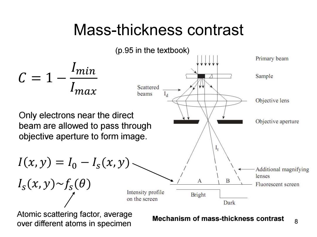
Mass-thickness contrast (p.95 in the textbook) Primary beam C=1- Imin Sample Imax Scattered beams Objective lens Only electrons near the direct Objective aperture beam are allowed to pass through objective aperture to form image. I(x,y)=1o-Is(x,y) Additional magnifying lenses Is(x,y)fs(e) A B Fluorescent screen Intensity profile Bright on the screen Dark Atomic scattering factor,average Mechanism of mass-thickness contrast over different atoms in specimen 8
Mass-thickness contrast Mechanism of mass 8 -thickness contrast Only electrons near the direct beam are allowed to pass through objective aperture to form image. 𝐶 = 1 − 𝐼𝑚𝑖𝑛 𝐼𝑚𝑎𝑥 𝐼 𝑥, 𝑦 = 𝐼0 − 𝐼𝑠(𝑥, 𝑦) 𝐼𝑠(𝑥, 𝑦)~𝑓𝑠(𝜃) Atomic scattering factor, average over different atoms in specimen (p.95 in the textbook)
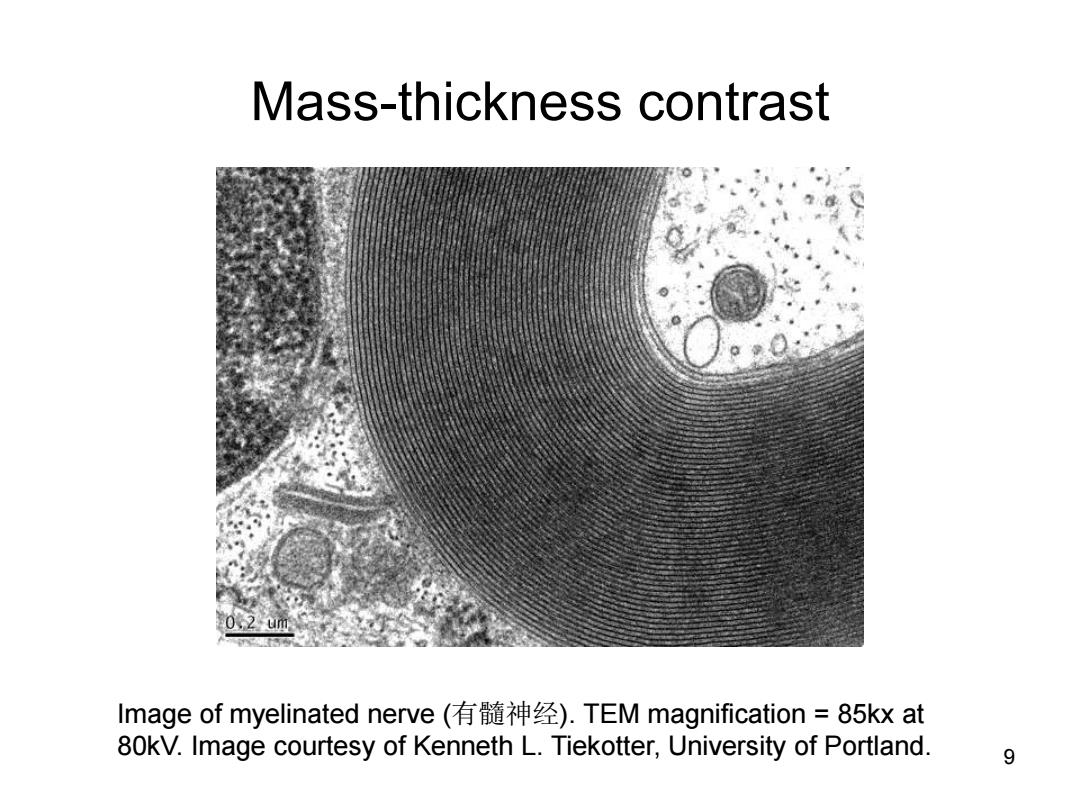
Mass-thickness contrast Image of myelinated nerve(有髓神经).TEM magnification=85kxat 80kV.Image courtesy of Kenneth L.Tiekotter,University of Portland. 9
Mass-thickness contrast 9 Image of myelinated nerve (有髓神经). TEM magnification = 85kx at 80kV. Image courtesy of Kenneth L. Tiekotter, University of Portland

Mechanism of mass thickness contrast Scattering but no explicit diffraction Amorphous specimen or disordered structure Glass,polymers,organic structures 10
Mechanism of mass thickness contrast • Scattering but no explicit diffraction • Amorphous specimen or disordered structure • Glass, polymers, organic structures 10