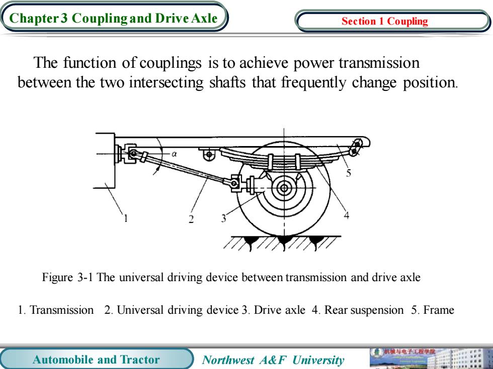
Chapter3 Coupling and Drive Axle Section 1 Coupling The function of couplings is to achieve power transmission between the two intersecting shafts that frequently change position. Figure 3-1 The universal driving device between transmission and drive axle 1.Transmission 2.Universal driving device 3.Drive axle 4.Rear suspension 5.Frame 机械与电子工程度 Automobile and Tractor Northwest A&F University
Automobile and Tractor Northwest A&F University Chapter 3 Coupling and Drive Axle The function of couplings is to achieve power transmission between the two intersecting shafts that frequently change position. Section 1 Coupling Figure 3-1 The universal driving device between transmission and drive axle 1. Transmission 2. Universal driving device 3. Drive axle 4. Rear suspension 5. Frame
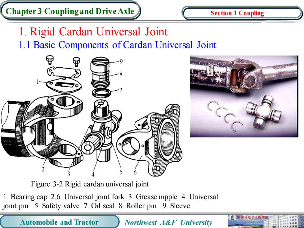
Chapter3 Coupling and Drive Axle Section 1 Coupling 1.Rigid Cardan Universal Joint 1.1 Basic Components of Cardan Universal Joint 甲 甲 9 Figure 3-2 Rigid cardan universal joint 1.Bearing cap 2,6.Universal joint fork 3.Grease nipple 4.Universal joint pin 5.Safety valve 7.Oil seal 8.Roller pin 9.Sleeve 械电子工程学酸 Automobile and Tractor Northwest A&F University
Automobile and Tractor Northwest A&F University Chapter 3 Coupling and Drive Axle 1. Rigid Cardan Universal Joint 1.1 Basic Components of Cardan Universal Joint Figure 3-2 Rigid cardan universal joint 1. Bearing cap 2,6. Universal joint fork 3. Grease nipple 4. Universal joint pin 5. Safety valve 7. Oil seal 8. Roller pin 9. Sleeve Section 1 Coupling

Chapter 3 Coupling and Drive Axle Section 1 Coupling 1.2 The Requirements of Constant Velocity for Double Cardan Universal Joint Figure 3-3 Constant speed drive arrangement of double cardan universal joint 1,3.driving fork 2,4.driven fork 2.Constant Velocity Universal Joint Figure 3-4 Fundamental principle of constant velocity universal joint 机城与电子工程度 Automobile and Tractor Northwest A&F University
Automobile and Tractor Northwest A&F University Chapter 3 Coupling and Drive Axle 1.2 The Requirements of Constant Velocity for Double Cardan Universal Joint 2. Constant Velocity Universal Joint Figure 3-3 Constant speed drive arrangement of double cardan universal joint 1,3. driving fork 2,4. driven fork Figure 3-4 Fundamental principle of constant velocity universal joint Section 1 Coupling
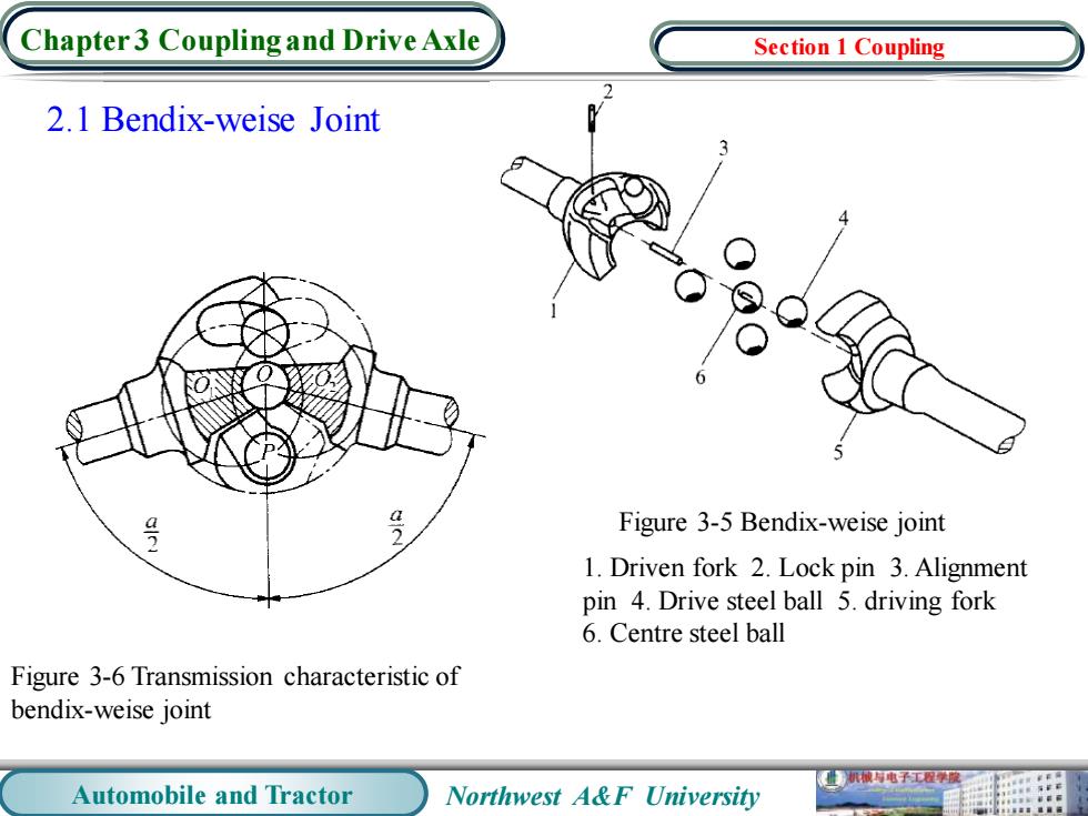
Chapter3 Coupling and Drive Axle Section 1 Coupling 2.1 Bendix-weise Joint 号 Figure 3-5 Bendix-weise joint 1.Driven fork 2.Lock pin 3.Alignment pin 4.Drive steel ball 5.driving fork 6.Centre steel ball Figure 3-6 Transmission characteristic of bendix-weise joint 业机械电子工程学度 Automobile and Tractor Northwest A&F University
Automobile and Tractor Northwest A&F University Chapter 3 Coupling and Drive Axle 2.1 Bendix-weise Joint Figure 3-6 Transmission characteristic of bendix-weise joint Figure 3-5 Bendix-weise joint 1. Driven fork 2. Lock pin 3. Alignment pin 4. Drive steel ball 5. driving fork 6. Centre steel ball Section 1 Coupling
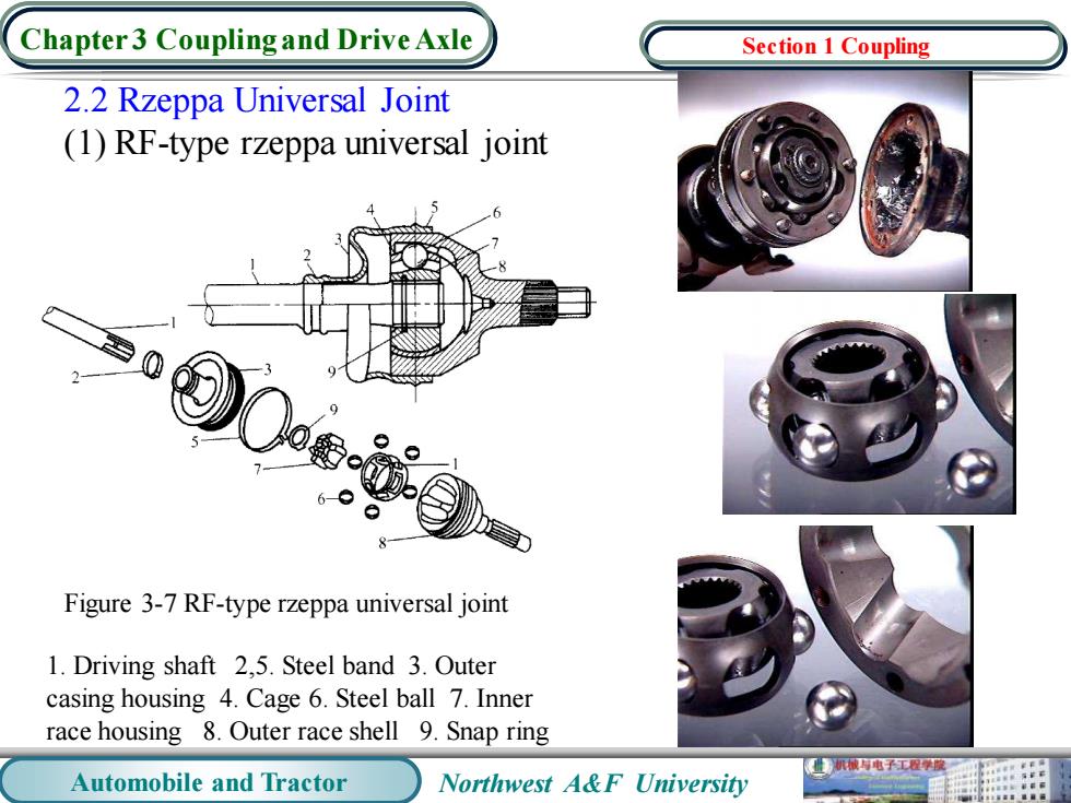
Chapter 3 Coupling and Drive Axle Section 1 Coupling 2.2 Rzeppa Universal Joint (1)RF-type rzeppa universal joint 6● Figure 3-7 RF-type rzeppa universal joint 1.Driving shaft 2,5.Steel band 3.Outer casing housing 4.Cage 6.Steel ball 7.Inner race housing 8.Outer race shell 9.Snap ring 机械与电子工容学聚 Automobile and Tractor Northwest A&F University
Automobile and Tractor Northwest A&F University Chapter 3 Coupling and Drive Axle 2.2 Rzeppa Universal Joint (1) RF-type rzeppa universal joint Figure 3-7 RF-type rzeppa universal joint 1. Driving shaft 2,5. Steel band 3. Outer casing housing 4. Cage 6. Steel ball 7. Inner race housing 8. Outer race shell 9. Snap ring Section 1 Coupling
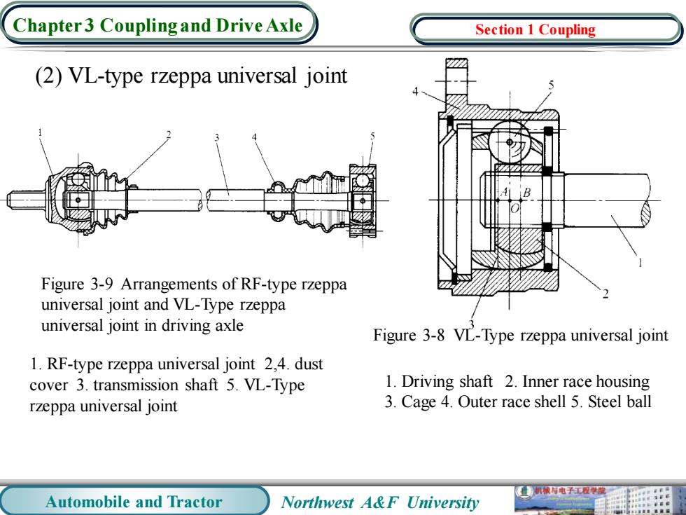
Chapter 3 Coupling and Drive Axle Section 1 Coupling (2)VL-type rzeppa universal joint B Figure 3-9 Arrangements of RF-type rzeppa universal joint and VL-Type rzeppa universal joint in driving axle Figure 3-8 VL-Type rzeppa universal joint 1.RF-type rzeppa universal joint 2,4.dust cover 3.transmission shaft 5.VL-Type 1.Driving shaft 2.Inner race housing rzeppa universal joint 3.Cage 4.Outer race shell 5.Steel ball 业机械电子工程学 Automobile and Tractor Northwest A&F University
Automobile and Tractor Northwest A&F University Chapter 3 Coupling and Drive Axle (2) VL-type rzeppa universal joint 1. Driving shaft 2. Inner race housing 3. Cage 4. Outer race shell 5. Steel ball Figure 3-8 VL-Type rzeppa universal joint Figure 3-9 Arrangements of RF-type rzeppa universal joint and VL-Type rzeppa universal joint in driving axle 1. RF-type rzeppa universal joint 2,4. dust cover 3. transmission shaft 5. VL-Type rzeppa universal joint Section 1 Coupling
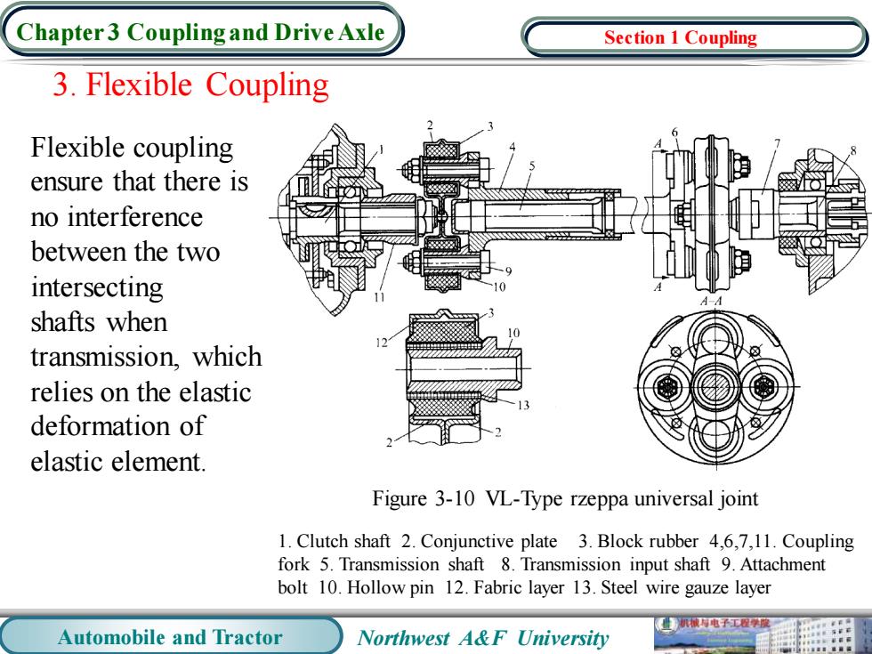
Chapter3 Coupling and Drive Axle Section 1 Coupling 3.Flexible Coupling Flexible coupling ensure that there is no interference between the two intersecting shafts when transmission,which relies on the elastic deformation of elastic element. Figure 3-10 VL-Type rzeppa universal joint 1.Clutch shaft 2.Conjunctive plate 3.Block rubber 4,6,7,11.Coupling fork 5.Transmission shaft 8.Transmission input shaft 9.Attachment bolt 10.Hollow pin 12.Fabric layer 13.Steel wire gauze layer 机被有电子工程学原 Automobile and Tractor Northwest A&F University
Automobile and Tractor Northwest A&F University Chapter 3 Coupling and Drive Axle 3. Flexible Coupling Flexible coupling ensure that there is no interference between the two intersecting shafts when transmission, which relies on the elastic deformation of elastic element. Figure 3-10 VL-Type rzeppa universal joint 1. Clutch shaft 2. Conjunctive plate 3. Block rubber 4,6,7,11. Coupling fork 5. Transmission shaft 8. Transmission input shaft 9. Attachment bolt 10. Hollow pin 12. Fabric layer 13. Steel wire gauze layer Section 1 Coupling
Chapter 3 Coupling and Drive Axle Section 2 Drive axle 1.Functions and Types of Drive Axles 1.1 Drive Axle and Their Function Automobiles'and tractors'drive axles are all transmission components and the shells between driving wheels and the transmission except drive shaft and coupling.The main functions of drive axles:First,they transmit engine torque came from the universal joint to the driving wheel through the final drive,differential, half-axle,etc.,and achieve to speed reduction and torque growth; Second,changing the direction of torque through the bevel gear pair of the final drive to make it parallel with the vehicle traveling direction; Third,ensuring that the speed of inside and outside wheels are not the same through the differential to achieve steering. 1.2 The Components and Types of Drive Axles Components:the final drive,differential,half-axle,housing,etc. 械电子工程学 Automobile and Tractor Northwest A&F University
Automobile and Tractor Northwest A&F University Chapter 3 Coupling and Drive Axle 1. Functions and Types of Drive Axles 1.1 Drive Axle and Their Function Automobiles’ and tractors’ drive axles are all transmission components and the shells between driving wheels and the transmission except drive shaft and coupling. The main functions of drive axles: First, they transmit engine torque came from the universal joint to the driving wheel through the final drive, differential, half-axle, etc., and achieve to speed reduction and torque growth; Second, changing the direction of torque through the bevel gear pair of the final drive to make it parallel with the vehicle traveling direction; Third, ensuring that the speed of inside and outside wheels are not the same through the differential to achieve steering. 1.2 The Components and Types of Drive Axles Components: the final drive, differential, half-axle, housing, etc.. Section 2 Drive axle
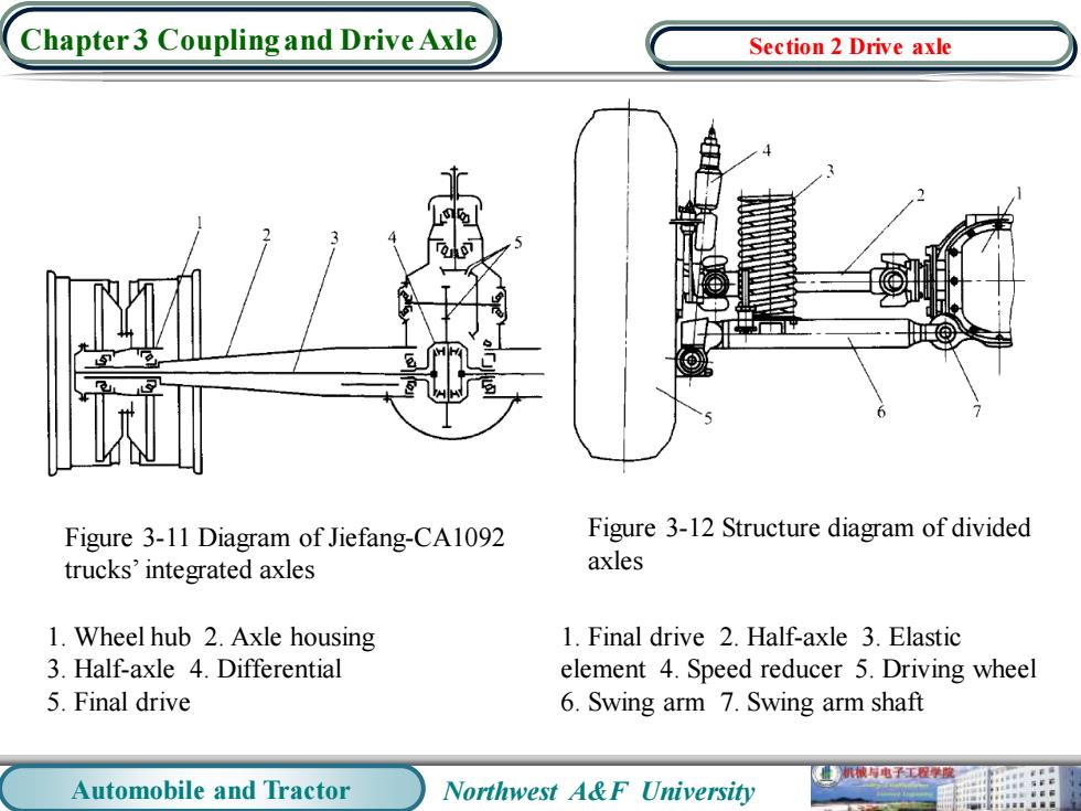
Chapter 3 Coupling and Drive Axle Section 2 Drive axle Figure 3-11 Diagram of Jiefang-CA1092 Figure 3-12 Structure diagram of divided trucks'integrated axles axles 1.Wheel hub 2.Axle housing 1.Final drive 2.Half-axle 3.Elastic 3.Half-axle 4.Differential element 4.Speed reducer 5.Driving wheel 5.Final drive 6.Swing arm 7.Swing arm shaft 机械持电子工程学膜 Automobile and Tractor Northwest A&F University
Automobile and Tractor Northwest A&F University Chapter 3 Coupling and Drive Axle Figure 3-11 Diagram of Jiefang-CA1092 trucks’ integrated axles Figure 3-12 Structure diagram of divided axles 1. Wheel hub 2. Axle housing 3. Half-axle 4. Differential 5. Final drive 1. Final drive 2. Half-axle 3. Elastic element 4. Speed reducer 5. Driving wheel 6. Swing arm 7. Swing arm shaft Section 2 Drive axle

Chapter3 Couplingand Drive Axle Section 2 Drive axle (a) (b) Figure 3-13 Structure diagram of wheeled tractors'rear axles 1.Main drive 2.Differential 3.Final drive 业机械电子工程学度 Automobile and Tractor Northwest A&F University
Automobile and Tractor Northwest A&F University Chapter 3 Coupling and Drive Axle Figure 3-13 Structure diagram of wheeled tractors’ rear axles 1. Main drive 2. Differential 3. Final drive Section 2 Drive axle