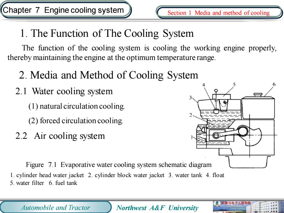
Chapter 7 Engine cooling system Section I Media and method of cooling 1.The Function of The Cooling System The function of the cooling system is cooling the working engine properly, thereby maintaining the engine at the optimum temperature range 2.Media and Method of Cooling System 2.1 Water cooling system (1)natural circulation cooling. (2)forced circulation cooling. 2.2 Air cooling system Figure 7.1 Evaporative water cooling system schematic diagram 1.cylinder head water jacket 2.cylinder block water jacket 3.water tank 4.float 5.water filter 6.fuel tank Automobile and Tractor Northwest A&F University
Automobile and Tractor Northwest A&F University Chapter 7 Engine cooling system 1. The Function of The Cooling System The function of the cooling system is cooling the working engine properly, therebymaintaining the engine at the optimum temperature range. 2. Media and Method of Cooling System 2.1 Water cooling system (1) natural circulation cooling. (2) forced circulation cooling. 2.2 Air cooling system Section 1 Media and method of cooling Figure 7.1 Evaporative water cooling system schematic diagram 1. cylinder head water jacket 2. cylinder block water jacket 3. water tank 4. float 5. water filter 6. fuel tank
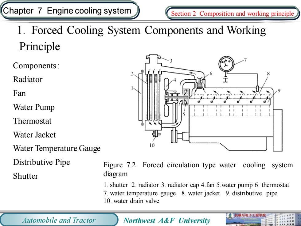
Chapter 7 Engine cooling system Section 2 Composition and working principle 1.Forced Cooling System Components and Working Principle Components: Radiator Fan Water Pump Thermostat Water Jacket Water Temperature Gauge 10 Distributive Pipe Figure 7.2 Forced circulation type water cooling system Shutter diagram 1.shutter 2.radiator 3.radiator cap 4.fan 5.water pump 6.thermostat 7.water temperature gauge 8.water jacket 9.distributive pipe 10.water drain valve 械电子工程学酸 Automobile and Tractor Northwest A&F University
Automobile and Tractor Northwest A&F University Chapter 7 Engine cooling system 1. Forced Cooling System Components and Working Principle Components : Radiator Fan Water Pump Thermostat Water Jacket Water Temperature Gauge Distributive Pipe Shutter Figure 7.2 Forced circulation type water cooling system diagram 1. shutter 2. radiator 3. radiator cap 4.fan 5.water pump 6. thermostat 7. water temperature gauge 8. water jacket 9. distributive pipe 10. water drain valve Section 2 Composition and working principle
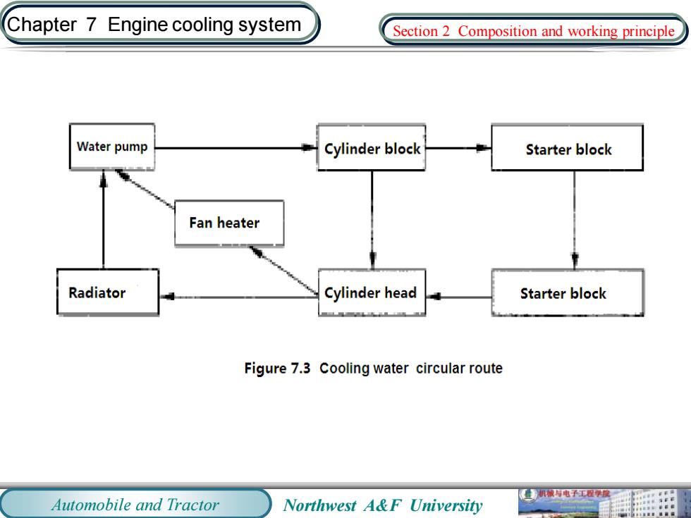
Chapter 7 Engine cooling system Section 2 Composition and working principle Water pump Cylinder block Starter block Fan heater Radiator Cylinder head Starter block Figure 7.3 Cooling water circular route 机械与电子工程学模二 Automobile and Tractor Northwest A&F University
Automobile and Tractor Northwest A&F University Chapter 7 Engine cooling system Section 2 Composition and working principle
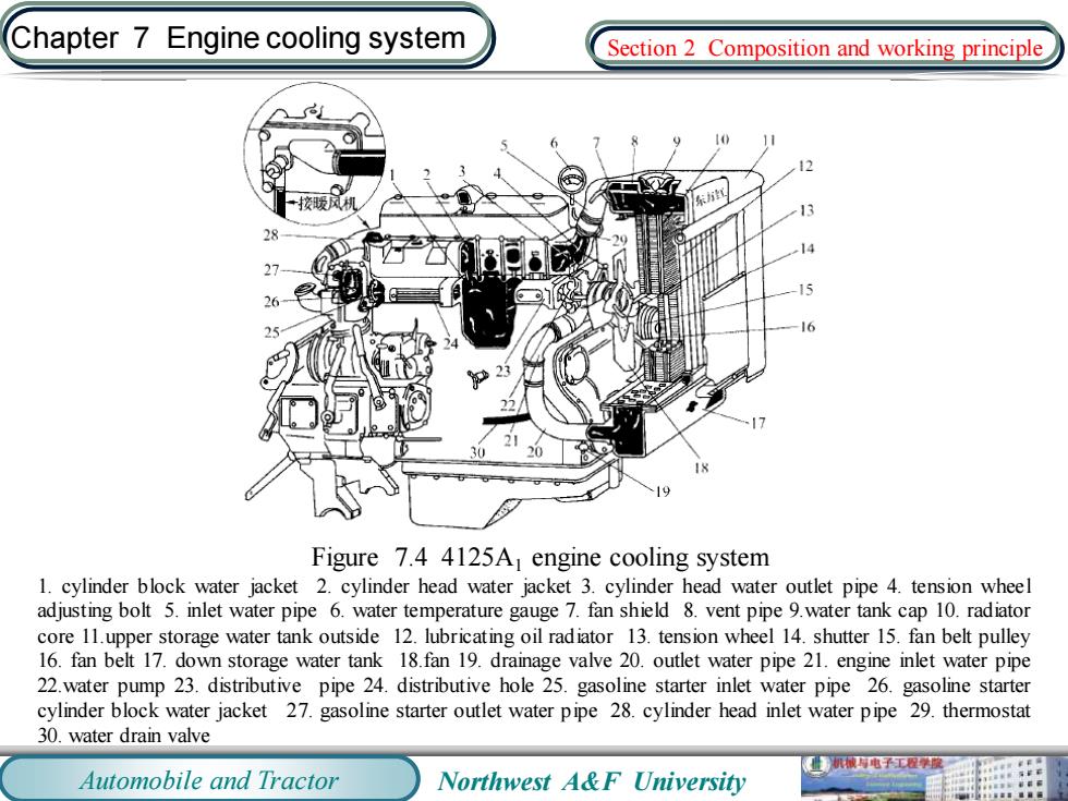
Chapter 7 Engine cooling system Section 2 Composition and working principle 东 Figure 7.4 4125A engine cooling system 1.cylinder block water jacket 2.cylinder head water jacket 3.cylinder head water outlet pipe 4.tension wheel adjusting bolt 5.inlet water pipe 6.water temperature gauge 7.fan shield 8.vent pipe 9.water tank cap 10.radiator core 11.upper storage water tank outside 12.lubricating oil radiator 13.tension wheel 14.shutter 15.fan belt pulley 16.fan belt 17.down storage water tank 18.fan 19.drainage valve 20.outlet water pipe 21.engine inlet water pipe 22.water pump 23.distributive pipe 24.distributive hole 25.gasoline starter inlet water pipe 26.gasoline starter cylinder block water jacket 27.gasoline starter outlet water pipe 28.cylinder head inlet water pipe 29.thermostat 30.water drain valve 业机电子工程学度 Automobile and Tractor Northwest A&F University
Automobile and Tractor Northwest A&F University Chapter 7 Engine cooling system Figure 7.4 4125A1 engine cooling system 1. cylinder block water jacket 2. cylinder head water jacket 3. cylinder head water outlet pipe 4. tension wheel adjusting bolt 5. inlet water pipe 6. water temperature gauge 7. fan shield 8. vent pipe 9.water tank cap 10. radiator core 11.upper storage water tank outside 12. lubricating oil radiator 13. tension wheel 14. shutter 15. fan belt pulley 16. fan belt 17. down storage water tank 18.fan 19. drainage valve 20. outlet water pipe 21. engine inlet water pipe 22.water pump 23. distributive pipe 24. distributive hole 25. gasoline starter inlet water pipe 26. gasoline starter cylinder block water jacket 27. gasoline starter outlet water pipe 28. cylinder head inlet water pipe 29. thermostat 30. water drain valve Section 2 Composition and working principle
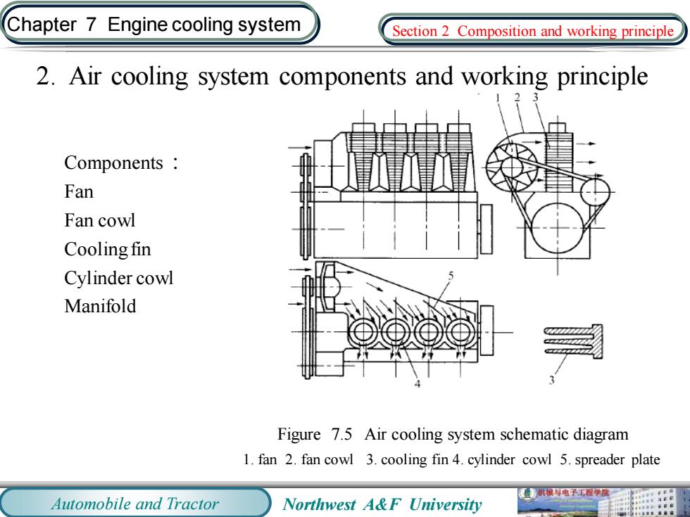
Chapter 7 Engine cooling system Section 2 Composition and working principle 2.Air cooling system components and working principle Components Fan Fan cowl Cooling fin Cylinder cowl Manifold Figure 7.5 Air cooling system schematic diagram 1.fan 2.fan cowl 3.cooling fin 4.cylinder cowl 5.spreader plate 机被电子工程学度 Automobile and Tractor Northwest A&F University
Automobile and Tractor Northwest A&F University Chapter 7 Engine cooling system 2. Air cooling system components and working principle Components : Fan Fan cowl Cooling fin Cylinder cowl Manifold Figure 7.5 Air cooling system schematic diagram 1. fan 2. fan cowl 3. cooling fin 4. cylinder cowl 5. spreader plate Section 2 Composition and working principle
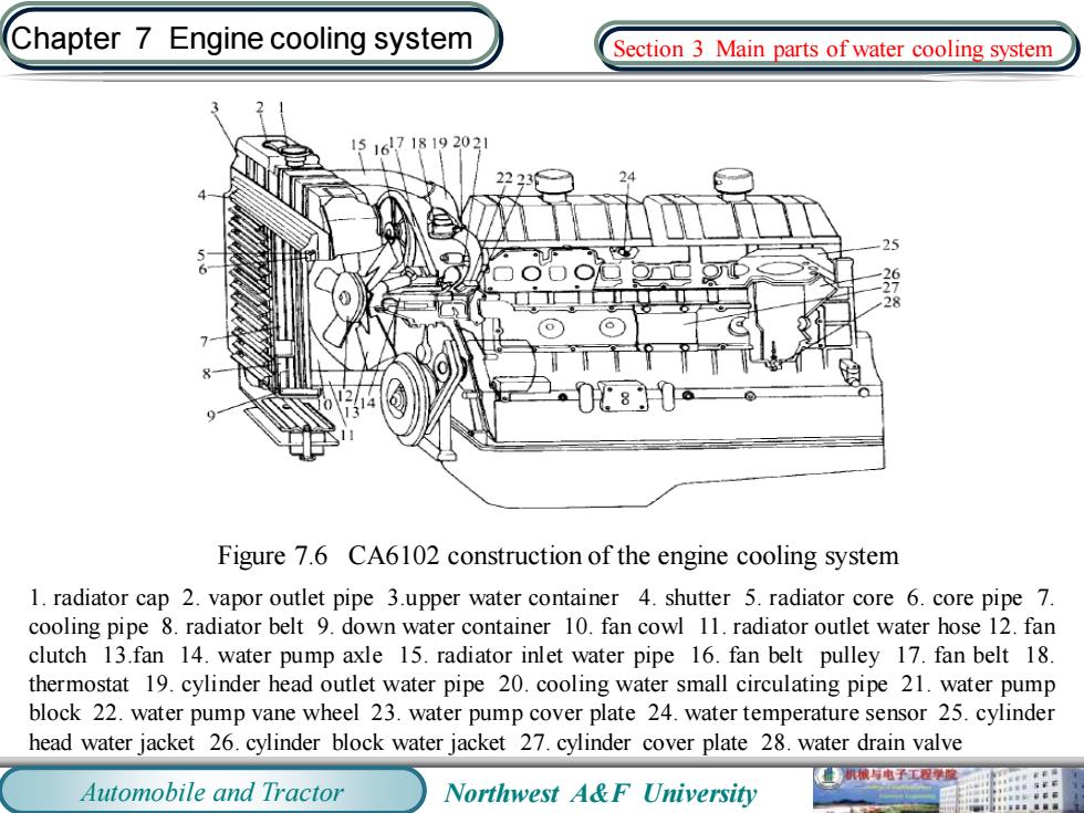
Chapter 7 Engine cooling system Section 3 Main parts of water cooling system 1516718192021 22231 08 Figure 7.6 CA6102 construction of the engine cooling system 1.radiator cap 2.vapor outlet pipe 3.upper water container 4.shutter 5.radiator core 6.core pipe 7. cooling pipe 8.radiator belt 9.down water container 10.fan cowl 11.radiator outlet water hose 12.fan clutch 13.fan 14.water pump axle 15.radiator inlet water pipe 16.fan belt pulley 17.fan belt 18. thermostat 19.cylinder head outlet water pipe 20.cooling water small circulating pipe 21.water pump block 22.water pump vane wheel 23.water pump cover plate 24.water temperature sensor 25.cylinder head water jacket 26.cylinder block water jacket 27.cylinder cover plate 28.water drain valve 机械与电子工程学 Automobile and Tractor Northwest A&F University
Automobile and Tractor Northwest A&F University Chapter 7 Engine cooling system Figure 7.6 CA6102 construction of the engine cooling system 1. radiator cap 2. vapor outlet pipe 3.upper water container 4. shutter 5. radiator core 6. core pipe 7. cooling pipe 8. radiator belt 9. down water container 10. fan cowl 11. radiator outlet water hose 12. fan clutch 13.fan 14. water pump axle 15. radiator inlet water pipe 16. fan belt pulley 17. fan belt 18. thermostat 19. cylinder head outlet water pipe 20. cooling water small circulating pipe 21. water pump block 22. water pump vane wheel 23. water pump cover plate 24. water temperature sensor 25. cylinder head water jacket 26. cylinder block water jacket 27. cylinder cover plate 28. water drain valve Section 3 Main parts of water cooling system

Chapter 7 Engine cooling system Section 3 Main parts of water cooling system 1.Water Pump The function of water pump forces the cooling water to accelerate the circulation to ensure a reliable engine cooling. Most engines use centrifugal water pumps.It is characterized by simple structure,large displacement,when the pump stops working for any reason, without prejudice to the natural cycle of cooling water Figure 7.7 Centrifugal water pump 1.water outlet port 2.vane wheel 3.water pump axle 4.shell 5.water inlet port 业机械与电子工程提 Automobile and Tractor Northwest A&F University
Automobile and Tractor Northwest A&F University Chapter 7 Engine cooling system 1. Water Pump The function of water pump forces the cooling water to accelerate the circulation to ensure a reliable engine cooling. Most engines use centrifugal water pumps. It is characterized by simple structure, large displacement, when the pump stops working for any reason, without prejudice to the natural cycle of coolingwater. Figure 7.7 Centrifugal water pump 1. water outlet port 2. vane wheel 3. water pump axle 4. shell 5. water inlet port Section 3 Main parts of water cooling system

Chapter 7 Engine cooling system Section 3 Main parts of water cooling system 10 f Figure 7.8 EQ6100-1 engine centrifugal water pump 1.water pump shell 2.vane wheel 3.fabric bakelite sealing washer 4.gasket 5.screw 6.sealing rubber cup 7.spring 8.gasket 9.pump cover 10.sealing seat ring 11.ball bearing 12.water pump axle 13 woodruff key 14.flange(used for the installation of pulley and fan)15.bearing clasp 16.spacer sleeve 17.grease nipple 18.water seal ring 19.pipe connector(used for connection of cylinder head outlet water pipe and cooling water small circulating pipe 业机械电子工程学二 Automobile and Tractor Northwest A&F University
Automobile and Tractor Northwest A&F University Chapter 7 Engine cooling system Figure 7.8 EQ6100-1 engine centrifugal water pump 1. water pump shell 2. vane wheel 3. fabric bakelite sealing washer 4. gasket 5. screw 6. sealing rubber cup 7.spring 8. gasket 9. pump cover 10. sealing seat ring 11. ball bearing 12. water pump axle 13. woodruff key 14. flange(used for the installation of pulley and fan) 15. bearing clasp 16. spacer sleeve 17. grease nipple 18. water seal ring 19. pipe connector(used for connection of cylinder head outlet water pipe and cooling water small circulating pipe ) Section 3 Main parts of water cooling system

Chapter 7 Engine cooling system Section 3 Main parts of water cooling system 2.Radiator Radiator is also known as water tank,its purpose is to cool the hot water from water jacket. The general requirements:after the radiator, water temperature should be reduced by 10- 15C.For the radiator,it must have sufficient cooling area and better thermal conductivity material Figure 7.9 Radiator 1.radiator cap 2.upper water container 3.radiator inlet water pipe 4.radiator core 5.radiator outlet water pipe 6.down water container 7.overflow pipe Automobile and Tractor Northwest A&F University
Automobile and Tractor Northwest A&F University Chapter 7 Engine cooling system 2. Radiator Radiator is also known as water tank, its purpose is to cool the hot water from water jacket. The general requirements: after the radiator, water temperature should be reduced by 10- 15℃.For the radiator, it must have sufficient cooling area and better thermal conductivity material. Figure 7.9 Radiator 1. radiator cap 2. upper water container 3. radiator inlet water pipe 4. radiator core 5. radiator outlet water pipe 6. down water container 7. overflow pipe Section 3 Main parts of water cooling system

Chapter 7 Engine cooling system Section 3 Main parts of water cooling system Figure 7.10 Fin and tube radiator core Figure 7.11 Ribbon-tubular radiator core 1.cooling pipe 2.cooling fin 1.radiator belt 2.cooling pipe 3.seam hole 械电子工程学度 Automobile and Tractor Northwest A&F University
Automobile and Tractor Northwest A&F University Chapter 7 Engine cooling system Figure 7.10 Fin and tube radiator core 1. cooling pipe 2. cooling fin Figure 7.11 Ribbon-tubular radiator core 1. radiator belt 2. cooling pipe 3. seam hole Section 3 Main parts of water cooling system