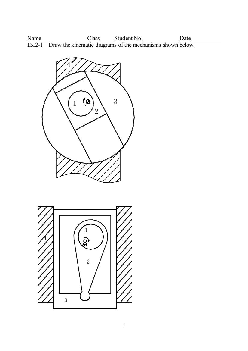
Name ClassStudent No. Date」 Ex.2-1 Draw the kinematic diagrams of the mechanisms shown below. 1 1 2
1 Name Class Student No. Date Ex.2-1 Draw the kinematic diagrams of the mechanisms shown below. 1 2 3 4 3 4 2 1
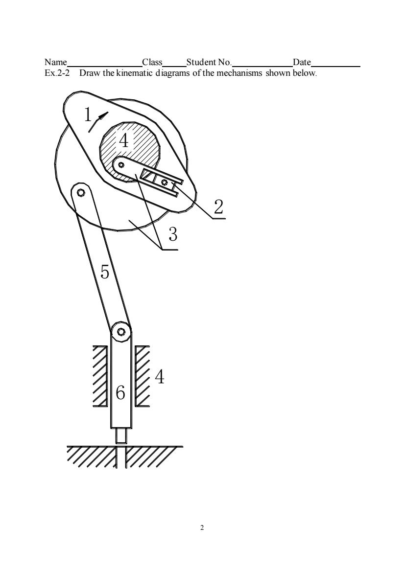
Name Class Student No. Date Ex.2-2 Draw the kinematic diagrams of the mechanisms shown below 4 2 3 5 4 6
2 Name Class Student No. Date Ex.2-2 Draw the kinematic diagrams of the mechanisms shown below. 1 2 3 4 5 6 4
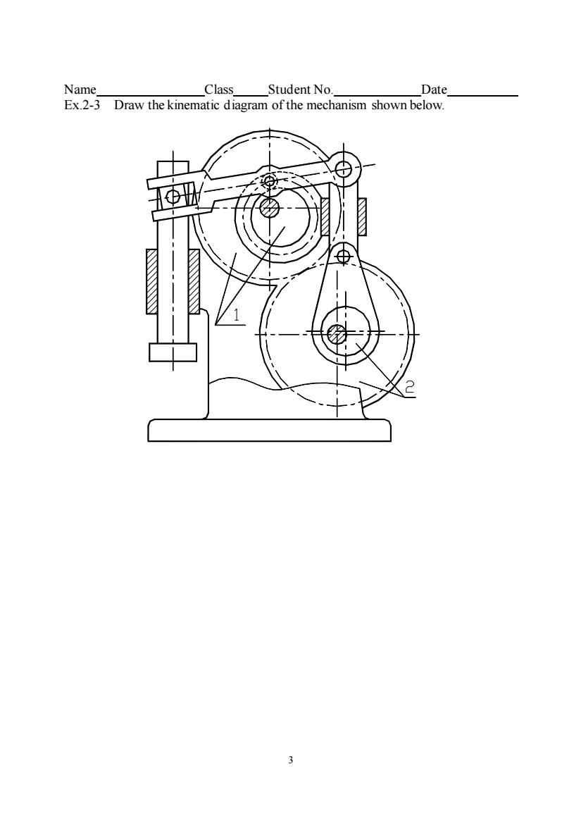
Name, Date. Ex.2-3 Draw the kinematic diagram of the mechanism shown below. Φ
3 Name Class Student No. Date Ex.2-3 Draw the kinematic diagram of the mechanism shown below
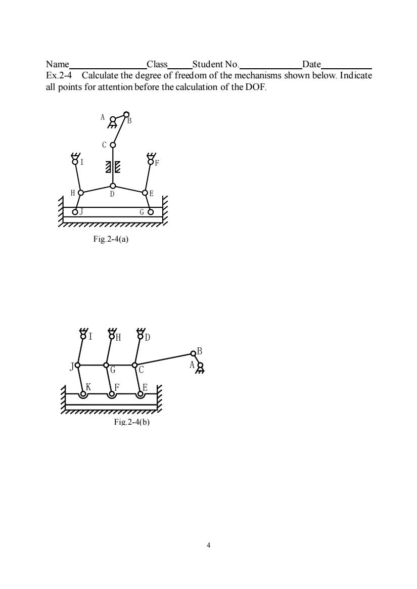
Name Class Student No. Date Ex.Calculate the degree of freedom of the mechanisms shown below.Indicate all points for attention before the calculation of the DOF. 777777777777777777 Fig.2-4(a) Fig.2-4(b)
4 Name Class Student No. Date Ex.2-4 Calculate the degree of freedom of the mechanisms shown below. Indicate all points for attention before the calculation of the DOF. A B C D E F G H I J Fig.2-4(a) A B C D F E G I H J K Fig.2-4(b)
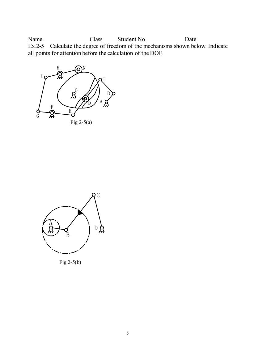
Name. Class Student No._ Date Ex.2-5 Calculate the degree of freedom of the mechanisms shown below.Indicate all points for attention before the calculation of the DOF. ⊙N 月 L Fig.2-5(a) Fig.2-5(b) 5
5 Name Class Student No. Date Ex.2-5 Calculate the degree of freedom of the mechanisms shown below. Indicate all points for attention before the calculation of the DOF. B D A Fig.2-5(b) A B C D E F G L M N O Fig.2-5(a)
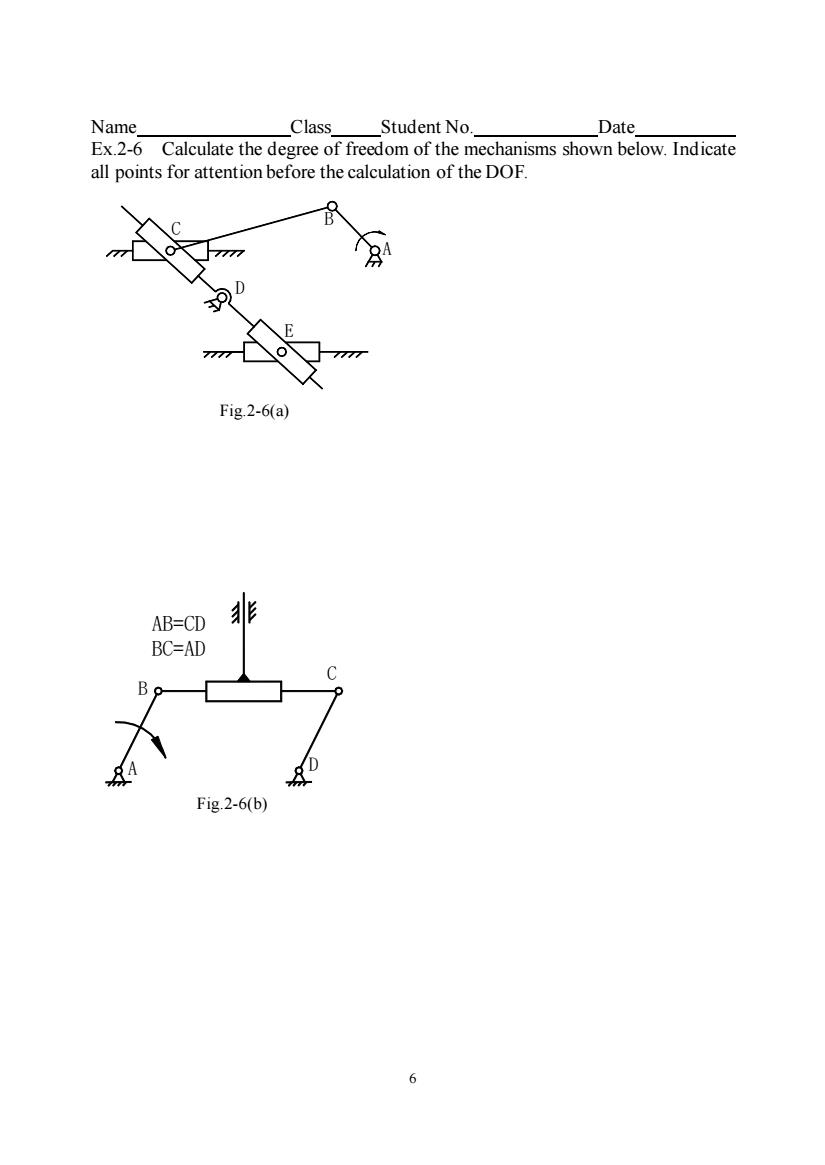
Name Class Student No. Date Ex Calculate the degree of freedom of the mechanisms shown below.Indicate all points for attention before the calculation of the DOF. Fig.2-6(a) AB=CD BC=AD Fig.2-6(b) 6
6 Name Class Student No. Date Ex.2-6 Calculate the degree of freedom of the mechanisms shown below. Indicate all points for attention before the calculation of the DOF. A B C D AB=CD BC=AD Fig.2-6(b) A B C D E Fig.2-6(a)
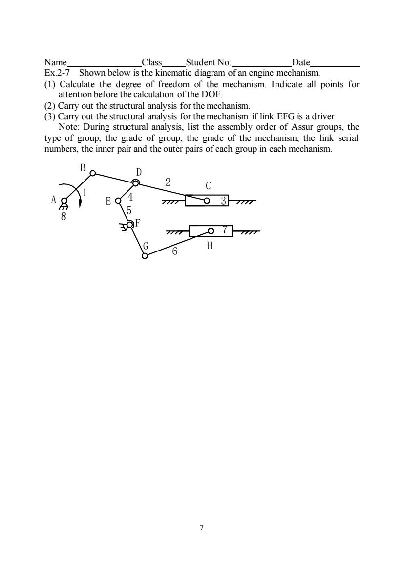
Name. Class Student No. Date Ex.2-7 Shown below is the kinematic diagram of an engine mechanism. (1)Calculate the degree of freedom of the mechanism.Indicate all points for attention before the calculation of the DOF. (2)Carry out the structural analysis for the mechanism. (3)Carry out the structural analysis for the mechanism if link EFG is a driver. Note:During structural analysis,list the assembly order of Assur groups,the type of group,the grade of group,the grade of the mechanism,the link serial numbers,the inner pair and the outer pairs ofeach group in each mechanism D 2 O/ 6 H
7 Name Class Student No. Date Ex.2-7 Shown below is the kinematic diagram of an engine mechanism. (1) Calculate the degree of freedom of the mechanism. Indicate all points for attention before the calculation of the DOF. (2) Carry out the structural analysis for the mechanism. (3) Carry out the structural analysis for the mechanism if link EFG is a driver. Note: During structural analysis, list the assembly order of Assur groups, the type of group, the grade of group, the grade of the mechanism, the link serial numbers, the inner pair and the outer pairs of each group in each mechanism. A B C D E F G H 1 2 3 4 6 5 7 8
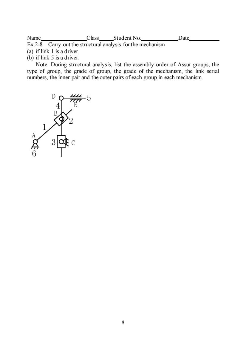
Name Class Student No. Date Ex.2-8 Carry out the structural analysis for the mechanism (a)if link 1 isadriver (b)if link 5 is a driver. Note:During structural analysis.list the assembly order of Assur groups.the 5 3C( 6
8 Name Class Student No. Date Ex.2-8 Carry out the structural analysis for the mechanism (a) if link 1 is a driver. (b) if link 5 is a driver. Note: During structural analysis, list the assembly order of Assur groups, the type of group, the grade of group, the grade of the mechanism, the link serial numbers, the inner pair and the outer pairs of each group in each mechanism. B 3 C 6 2 1 A D 4 5 E
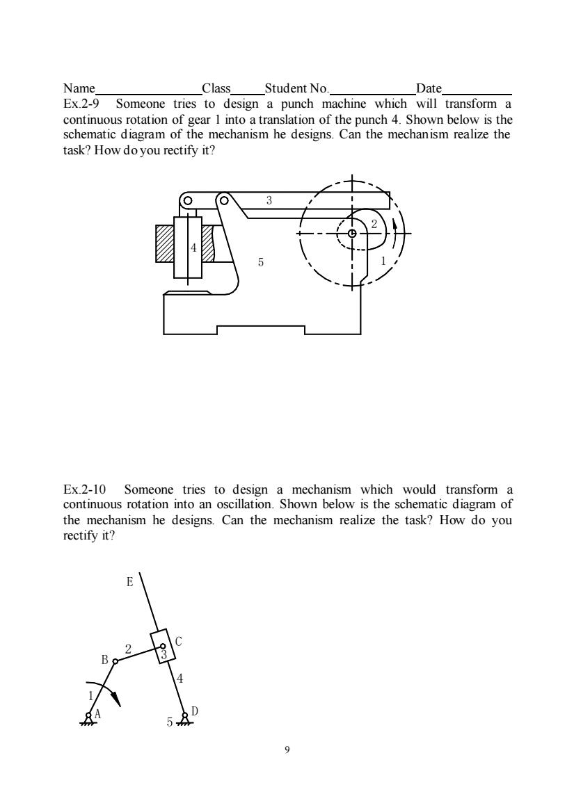
Name. Class Student No. Date Ex.2-9 Someone tries to design a punch machine which will transform a of gear 1into atranslation of the punch 4.Shown below is the schen mechanism he designs.Can the mechanism realize the task?How do you rectify it? Ex.2-10 Someone tries to design a mechanism which would transform a continuous rotation into an oscillation.Shown below is the schematic diagram of the mechanism he designs.Can the mechanism realize the task?How do you rectify it? E 9
9 Name Class Student No. Date Ex.2-9 Someone tries to design a punch machine which will transform a continuous rotation of gear 1 into a translation of the punch 4. Shown below is the schematic diagram of the mechanism he designs. Can the mechanism realize the task? How do you rectify it? Ex.2-10 Someone tries to design a mechanism which would transform a continuous rotation into an oscillation. Shown below is the schematic diagram of the mechanism he designs. Can the mechanism realize the task? How do you rectify it? A D B C E 1 2 3 4 1 2 3 4 5
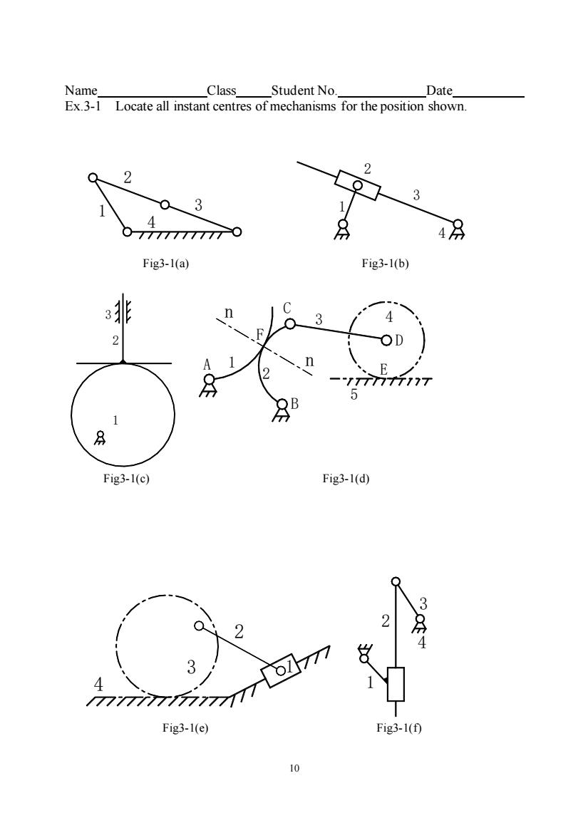
Name Class Student No. Date Ex.3-1 Locate all instant centres of mechanisms for the position shown 2 4 4 Fig3-l(a) Fig3-l(b) OD 75 Fig3-1(c) Fig3-1(d) 3 2 3 Fig3-l(e) Fig3-1(0
10 Name Class Student No. Date Ex.3-1 Locate all instant centres of mechanisms for the position shown. 1 2 3 4 1 4 2 3 Fig3-1(e) Fig3-1(f) 2 1 3 4 1 2 3 4 Fig3-1(a) Fig3-1(b) 2 3 1 3 B A 1 2 n n F C 5 E 4 D Fig3-1(c) Fig3-1(d)