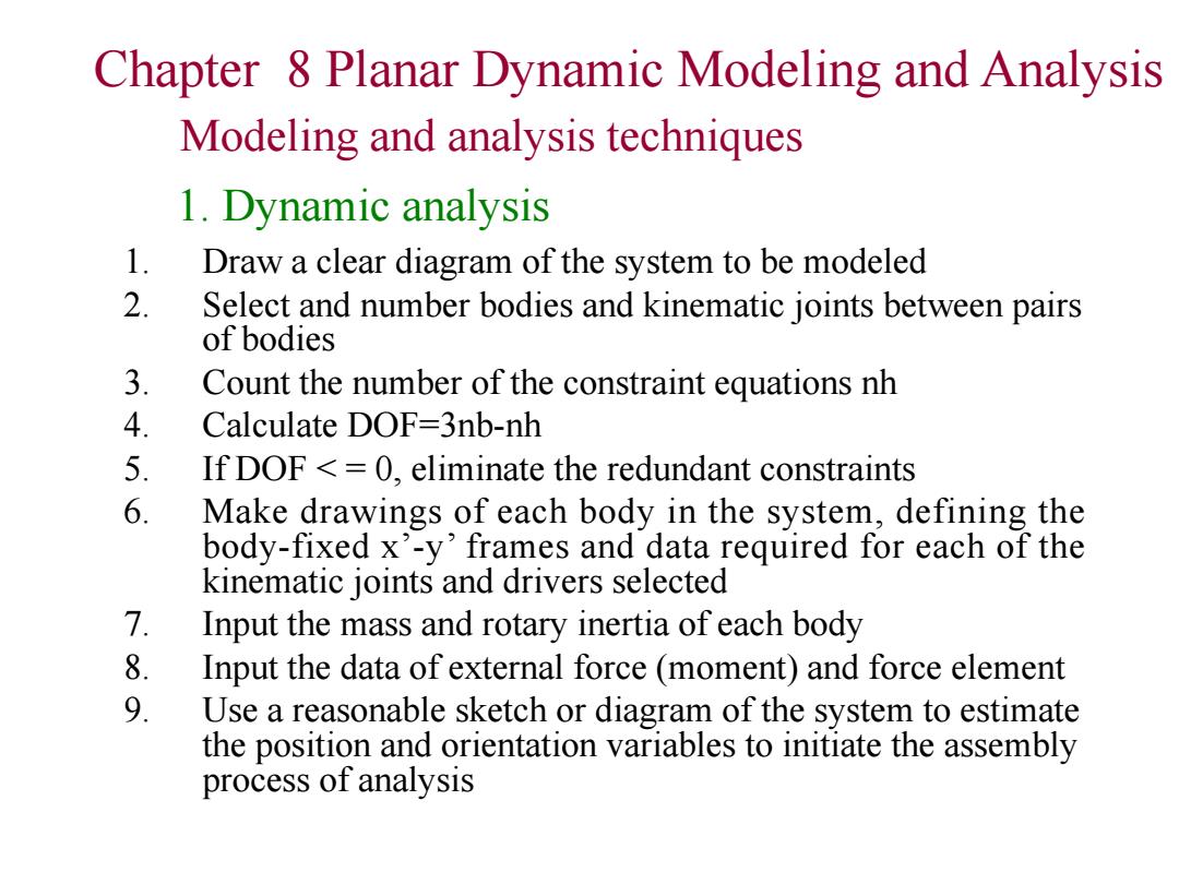
Chapter 8 Planar Dynamic Modeling and Analysis Modeling and analysis techniques 1.Dynamic analysis 1. Draw a clear diagram of the system to be modeled 2. Select and number bodies and kinematic joints between pairs of bodies 3. Count the number of the constraint equations nh 4. Calculate DOF=3nb-nh 5. If DOF<=0,eliminate the redundant constraints 6. Make drawings of each body in the system,defining the body-fixed x'-y'frames and data required for each of the kinematic joints and drivers selected 7. Input the mass and rotary inertia of each body 8. Input the data of external force(moment)and force element 9. Use a reasonable sketch or diagram of the system to estimate the position and orientation variables to initiate the assembly process of analysis
Chapter 8 Planar Dynamic Modeling and Analysis 1. Draw a clear diagram of the system to be modeled 2. Select and number bodies and kinematic joints between pairs of bodies 3. Count the number of the constraint equations nh 4. Calculate DOF=3nb-nh 5. If DOF < = 0, eliminate the redundant constraints 6. Make drawings of each body in the system, defining the body-fixed x’-y’ frames and data required for each of the kinematic joints and drivers selected 7. Input the mass and rotary inertia of each body 8. Input the data of external force (moment) and force element 9. Use a reasonable sketch or diagram of the system to estimate the position and orientation variables to initiate the assembly process of analysis Modeling and analysis techniques 1. Dynamic analysis

Chapter 8 Planar Dynamic Modeling and Analysis Modeling and analysis techniques 2.Inverse dynamic analysis 1. Draw a clear diagram of the system to be modeled 2. Select and number bodies and kinematic joints between pairs of bodies 3. Count the number of the constraint equations nh 4. Calculate DOF=3nb-nh 5. If DOF <=0,eliminate the redundant constraints 6. Define the driving constraints 7. Make drawings of each body in the system,defining the body-fixed x'-y'frames and data required for each of the kinematic joints and drivers selected 8. Input the mass and rotary inertia of each body 9. Input the data of external force(moment)and force element 10 Use a reasonable sketch or diagram of the system to estimate the position and orientation variables to initiate the assembly process of analysis
Chapter 8 Planar Dynamic Modeling and Analysis Modeling and analysis techniques 2. Inverse dynamic analysis 1. Draw a clear diagram of the system to be modeled 2. Select and number bodies and kinematic joints between pairs of bodies 3. Count the number of the constraint equations nh 4. Calculate DOF=3nb-nh 5. If DOF < = 0, eliminate the redundant constraints 6. Define the driving constraints 7. Make drawings of each body in the system, defining the body-fixed x’-y’ frames and data required for each of the kinematic joints and drivers selected 8. Input the mass and rotary inertia of each body 9. Input the data of external force (moment) and force element 10. Use a reasonable sketch or diagram of the system to estimate the position and orientation variables to initiate the assembly process of analysis

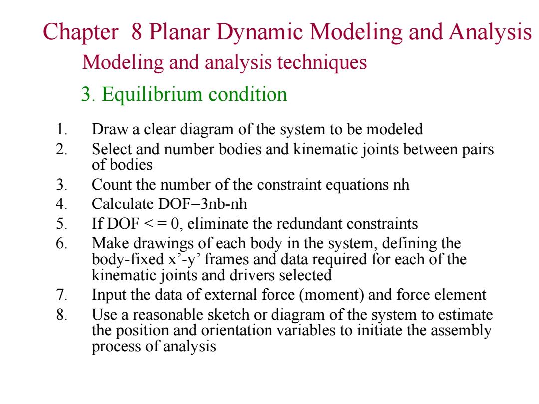
Chapter 8 Planar Dynamic Modeling and Analysis Modeling and analysis techniques 3.Equilibrium condition 1. Draw a clear diagram of the system to be modeled 2. Select and number bodies and kinematic joints between pairs of bodies 3. Count the number of the constraint equations nh 4. Calculate DOF=3nb-nh 5. If DOF <=0,eliminate the redundant constraints 6. Make drawings of each body in the system,defining the body-fixed x'-y'frames and data required for each of the kinematic joints and drivers selected 7. Input the data of external force(moment)and force element 8. Use a reasonable sketch or diagram of the system to estimate the position and orientation variables to initiate the assembly process of analysis
Chapter 8 Planar Dynamic Modeling and Analysis Modeling and analysis techniques 3. Equilibrium condition 1. Draw a clear diagram of the system to be modeled 2. Select and number bodies and kinematic joints between pairs of bodies 3. Count the number of the constraint equations nh 4. Calculate DOF=3nb-nh 5. If DOF < = 0, eliminate the redundant constraints 6. Make drawings of each body in the system, defining the body-fixed x’-y’ frames and data required for each of the kinematic joints and drivers selected 7. Input the data of external force (moment) and force element 8. Use a reasonable sketch or diagram of the system to estimate the position and orientation variables to initiate the assembly process of analysis