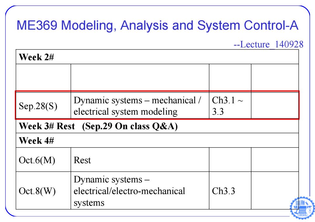
ME369 Modeling,Analysis and System Control-A --Lecture 140928 Week 2# Dynamic systems-mechanical Ch3.1~ Sep.28(S) electrical system modeling 3.3 Week 3#Rest (Sep.29 On class Q&A) Week 4# 0ct.6M)) Rest Dynamic systems- Oct.8(W) electrical/electro-mechanical Ch3.3 systems
ME369 Modeling, Analysis and System Control-A --Lecture_140928 Week 2# Sep.28(S) Dynamic systems – mechanical / electrical system modeling Ch3.1 ~ 3.3 Week 3# Rest (Sep.29 On class Q&A) Week 4# Oct.6(M) Rest Oct.8(W) Dynamic systems – electrical/electro-mechanical systems Ch3.3
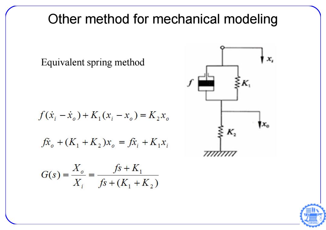
Other method for mechanical modeling Equivalent spring method X 多K f(-元。)+K(x;-x。)=K2x。 K 。+(K1+K2)x。=+K1x 7777 G(s)- 。= fs+K X,尽+(K1+K2)
Other method for mechanical modeling Equivalent spring method
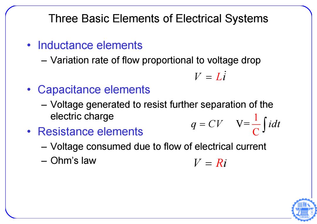
Three Basic Elements of Electrical Systems ·Inductance elements Variation rate of flow proportional to voltage drop V=Li Capacitance elements Voltage generated to resist further separation of the electric charge ·Resistance elements g=Crv=己打 Voltage consumed due to flow of electrical current Ohm's law V=Ri
Three Basic Elements of Electrical Systems • Inductance elements – Variation rate of flow proportional to voltage drop • Capacitance elements – Voltage generated to resist further separation of the electric charge • Resistance elements – Voltage consumed due to flow of electrical current – Ohm’s law V i L V 1 C q CV idt = V i R
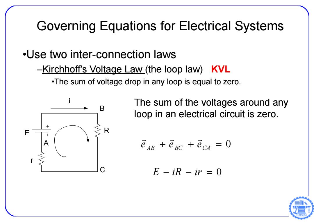
Governing Equations for Electrical Systems .Use two inter-connection laws -Kirchhoff's Voltage Law_(the loop law)KVL .The sum of voltage drop in any loop is equal to zero. The sum of the voltages around any B loop in an electrical circuit is zero. E R ean +eac +eca =O C E-iR-ir =0
Governing Equations for Electrical Systems •Use two inter-connection laws –Kirchhoff's Voltage Law (the loop law) KVL •The sum of voltage drop in any loop is equal to zero. The sum of the voltages around any loop in an electrical circuit is zero. 0 AB BC CA e e e E iR ir 0 E B C A i R r
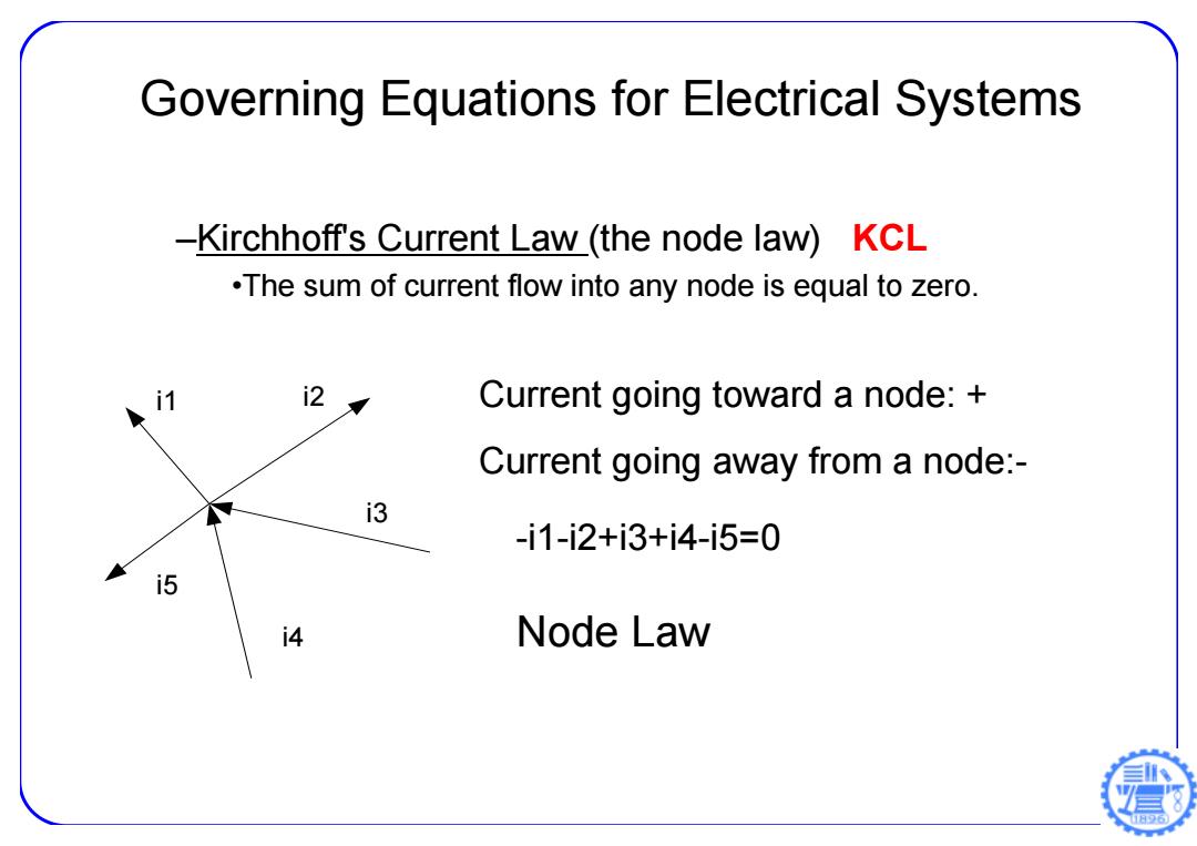
Governing Equations for Electrical Systems -Kirchhoff's Current Law (the node law)KCL .The sum of current flow into any node is equal to zero. i2 Current going toward a node: Current going away from a node:- i3 -i1-i2+i3+i4-i5=0 i5 4 Node Law
–Kirchhoff's Current Law (the node law) KCL •The sum of current flow into any node is equal to zero. i1 i2 i3 i4 i5 Current going toward a node: + Current going away from a node:- -i1-i2+i3+i4-i5=0 Node Law Governing Equations for Electrical Systems
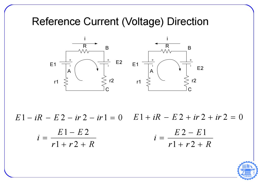
Reference Current (Voltage)Direction R B R B E2 E1 A E2 1 >r2 r1 r2 E1-iR-E2-ir2-ir1=0 E1+iR-E2+ir2+ir2=0 E1-E2 E2-E1 i= i r1+r2+R rl+r2+R
Reference Current (Voltage) Direction E 1 iR E 2 ir 2 ir 1 0 E1 B C A i R r1 r2 E2 E1 B C A i R r1 r2 E2 r r R E E i 1 2 1 2 E 1 iR E 2 ir 2 ir 2 0 r r R E E i 1 2 2 1

Reference Current (Voltage)direction i1 A i2 ↑i3 E1-E2+R2i3-Ri1=0 E1 E2 E2-R3i2-R2i3=0 R3 E1-R,i2-Ri1=0 R1 R2 i1+i3=i2 B 日96
Reference Current (Voltage) direction 1 2 0 E E R 2 i 3 R1i1 E1 B A i1 i2 i3 E2 R1 R2 R3 2 0 E R 3 i 2 R 2 i 3 E 1 R 3 i 2 R1i1 0 1 3 2 i i i
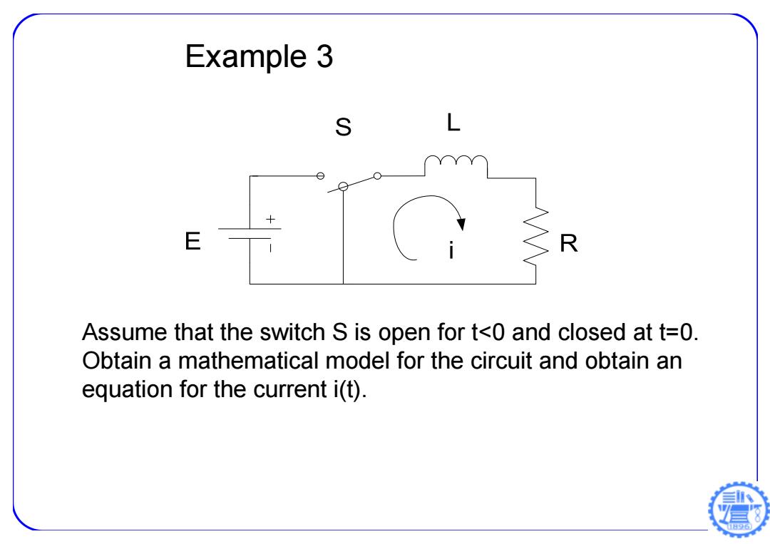
Example 3 S L E R Assume that the switch S is open for t<0 and closed at t=0. Obtain a mathematical model for the circuit and obtain an equation for the current i(t). 6
Example 3 Assume that the switch S is open for t<0 and closed at t=0. Obtain a mathematical model for the circuit and obtain an equation for the current i(t)
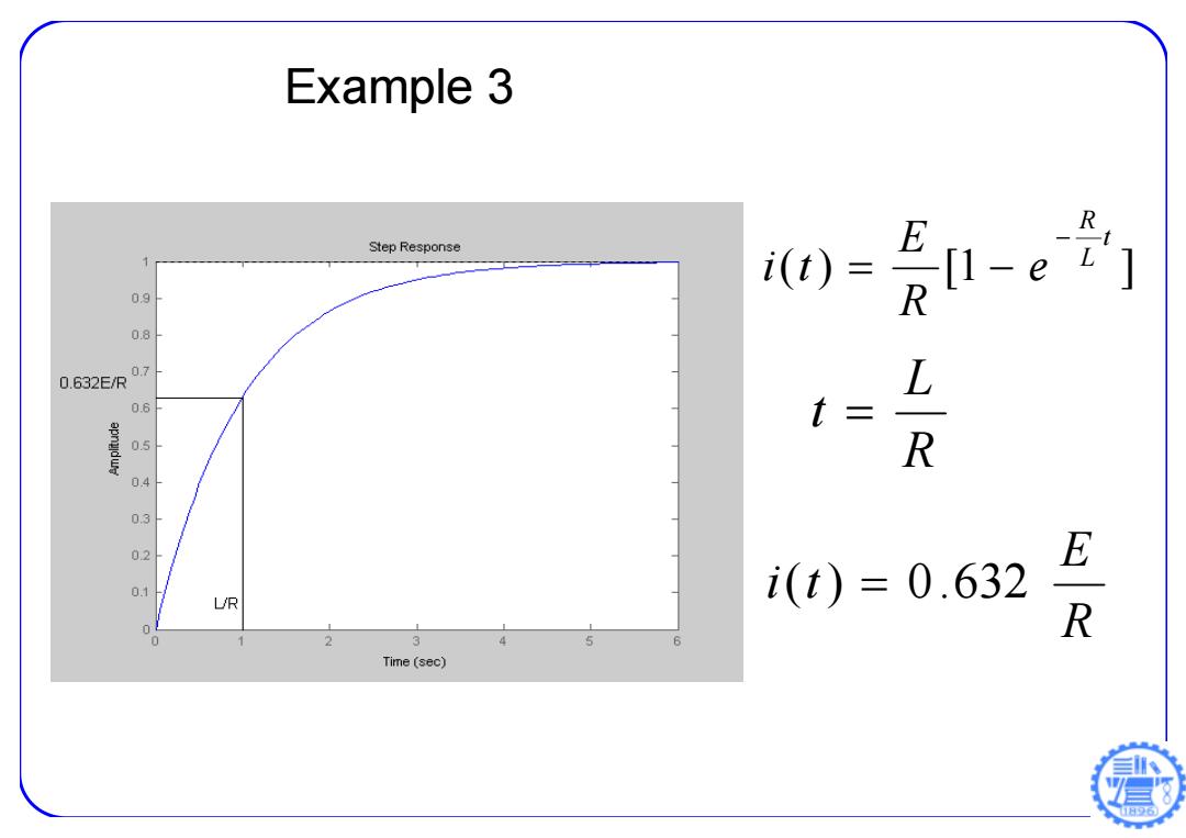
Example 3 E R Step Response i(t) [1-e ] 09 R 08 0.7 0.632E/R L 06 t= 0.5 R 0.4 03 02 E 0.1 i(t)=0.632 UR 0 R 0 2 3 4 5 6 Time(sec)
( ) [1 ] t L R e R E i t R L t R E i(t) 0.632 Example 3

Example 4 S E R Assume that the switch S is open for t0.Obtain a mathematical model for the circuit and obtain an equation for the current i(t). 日6
Example 4 Assume that the switch S is open for t0. Obtain a mathematical model for the circuit and obtain an equation for the current i(t)