ME369 Modeling,Analysis and System Control-A --Lecture 141008 Week 4# Oct.6(M) Rest Oct.8(W) Dynamic systems-electrical Ch3.3 /electro-mechanical systems Week 5# Ch2.1~ Oct.13M)) Transfer function,block diagram HW2 due 2.3 Signal Flow Graphs Oct.15(W) Ch3.9, HW3 Linearization 3.10(4)
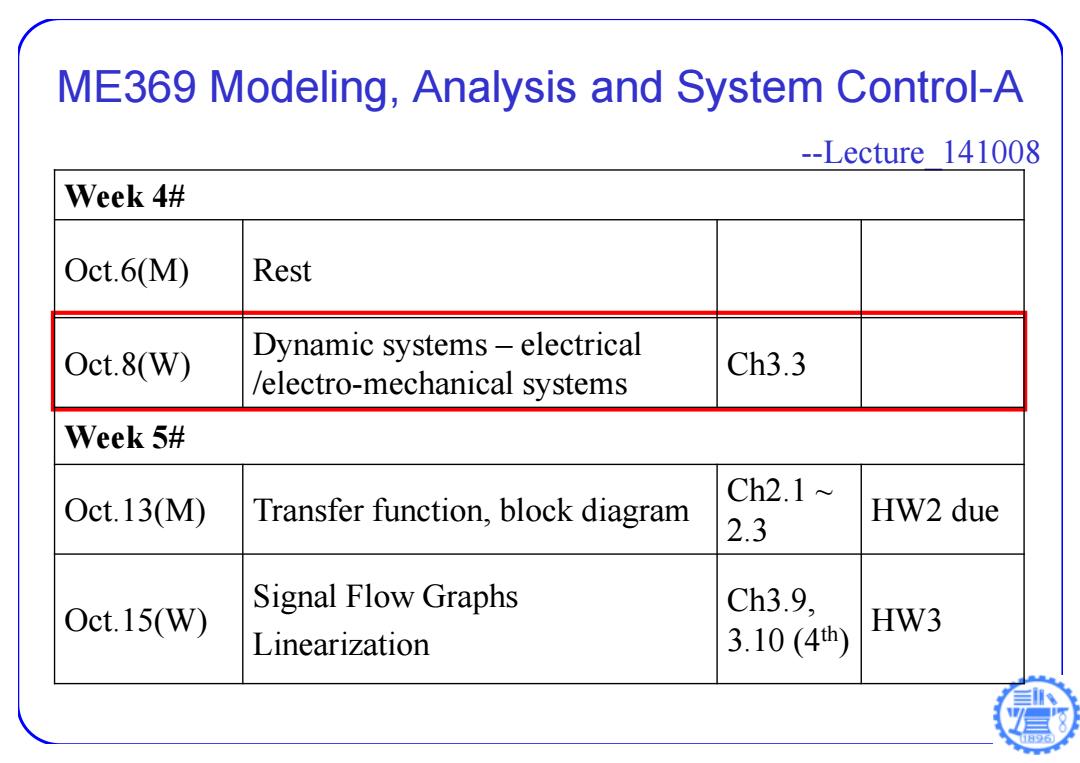
ME369 Modeling, Analysis and System Control-A --Lecture_141008 Week 4# Oct.6(M) Rest Oct.8(W) Dynamic systems – electrical /electro-mechanical systems Ch3.3 Week 5# Oct.13(M) Transfer function, block diagram Ch2.1 ~ 2.3 HW2 due Oct.15(W) Signal Flow Graphs Linearization Ch3.9, 3.10 (4th ) HW3
DC Servo-Motor Ra G I,=constant R3=armature resistance,2电枢电阻 i=field current,A La=armature inductance,H,电枢电感 激磁电流 ia=armature current,.A,电枢电流
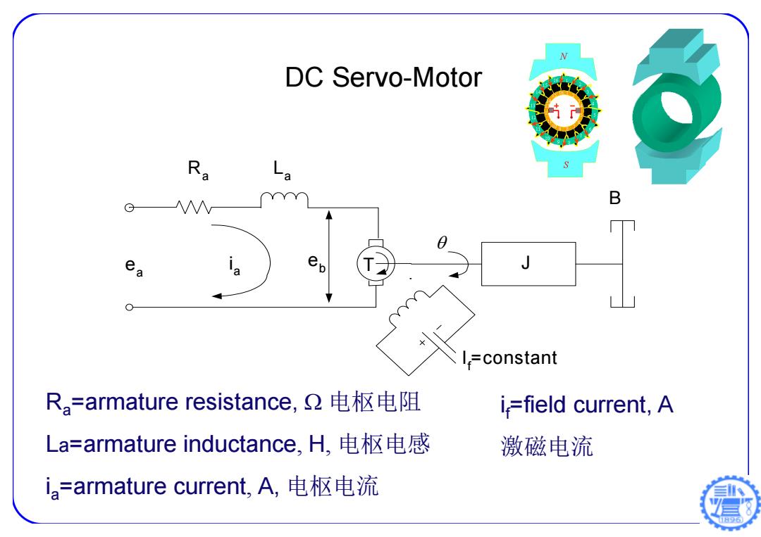
ea B La If=constant Ra eb T J ia Ra=armature resistance, 电枢电阻 La=armature inductance, H, 电枢电感 ia=armature current, A, 电枢电流 if=field current, A 激磁电流 DC Servo-Motor
ea=applied armature voltage,V电枢控制电压 e,=back emf(electromotive force),V感应反电动势 d=angular displacement of the motor shaft,.rad电机轴上的角位移 T=torque developed by the motor.N-m电机力矩。 J=moment of inertia of the motor and load referred to the motor shaft.Kg-m2电机转子和负载的惯量。 b=viscous-friction coefficient of the motor and load referred to the motor shaft.N-m/rad/s.电机转子和负载的粘性摩擦系数。 Ra L B G =constant
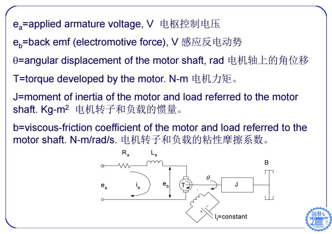
ea=applied armature voltage, V 电枢控制电压 eb=back emf (electromotive force), V 感应反电动势 =angular displacement of the motor shaft, rad 电机轴上的角位移 T=torque developed by the motor. N-m 电机力矩。 J=moment of inertia of the motor and load referred to the motor shaft. Kg-m2 电机转子和负载的惯量。 b=viscous-friction coefficient of the motor and load referred to the motor shaft. N-m/rad/s. 电机转子和负载的粘性摩擦系数。 ea B La If=constant Ra eb T J ia
Four Governing Equations for DC Servo Motor T=Kria Kr:torque constant do e6=K6 di Kp:back emf constant. La ia+Ri。+ew=ea 6 d20 =T=Kria 日6
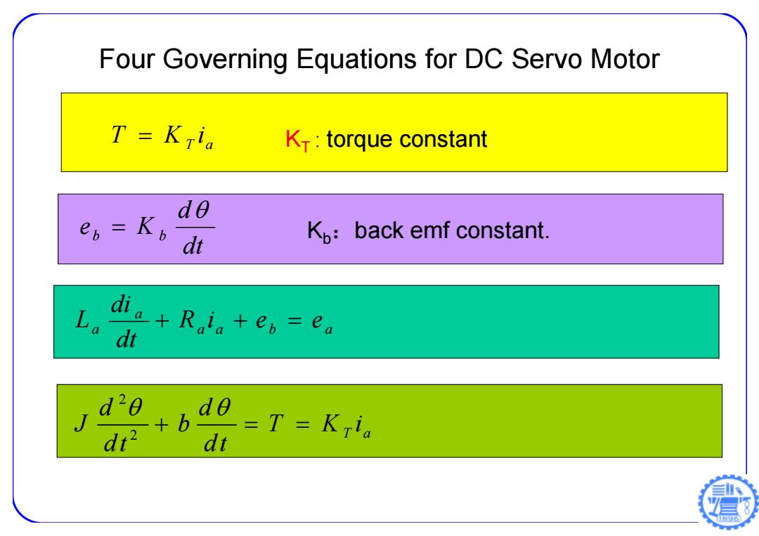
KT T Ki T a : torque constant dt d eb K b Kb:back emf constant. Four Governing Equations for DC Servo Motor a a b a a a R i e e dt di L 2 2 T a d d J b T Ki dt dt
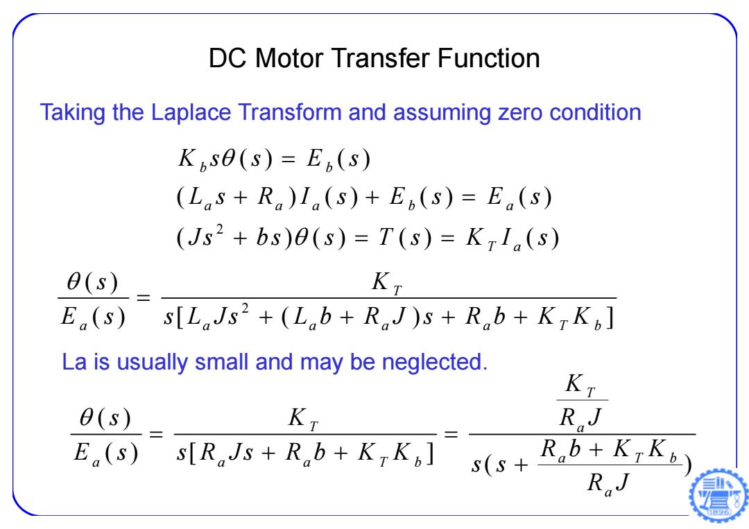
DC Motor Transfer Function Taking the Laplace Transform and assuming zero condition Kise(s)=E(s) (Las+R)Ia(s)+En(s)=E(s) (Js2+bs)e(s)=T(s)=K71(s) 0(s) KT E(s) s[LJs2+(Lob+RJ)s+Rob+KTK] La is usually small and may be neglected. θ(s) KT RJ E(s) sTRJs+Rb+k,k s(s4RbtKk RaJ
Taking the Laplace Transform and assuming zero condition 2 () () ( ) () () () ( ) () () () b b a aa b a T a Ks s E s L s RIs Es Es Js bs s T s K I s DC Motor Transfer Function 2 ( ) () [ ( ) ] T a a a a a Tb s K E s s L Js L b R J s R b K K La is usually small and may be neglected. ( ) () [ ] ( ) T T a a Tb a a a Tb a K s K R J E s s R Js R b K K Rb K K s s R J
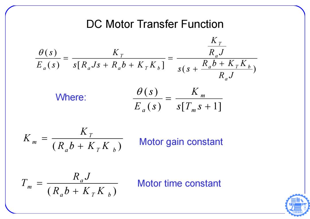
DC Motor Transfer Function Kt 0(s) KT RJ E(s) s[RJs+Rb+KTK] s(S+ R.b+KiK5) RJ Where: θ(s) Km E(s) s[T,s+1] Km KT (Rb+KTK) Motor gain constant Tm RJ Motor time constant (Rb+KTK
( ) [ 1] ( ) s T s K E s s m m a Where: ( ) T m a Tb K K Rb K K ( ) a m a Tb R J T Rb K K Motor gain constant Motor time constant DC Motor Transfer Function ( ) () [ ] ( ) T T a a Tb a a a Tb a K s K R J E s s R Js R b K K R b KK s s R J

DC Motor Specification θ(s) KT E(s)s[LJs2+(Lob+RJ)s+Rb+KK] 148866 148867 148877 Motor Data Vafues at nominal voltage 1 Nominal voltage V 12.0 24.0 48.0 0(s) Km 2 No load speed rpm 6920 7580 7580 3 No load current mA 241 137 68.6 E(s) s[Ts+1] 4 Nominal speed rpm 6370 6930 7000 5 Nominal torque(max.continuous torque) mNm 94.9 170 184 6 Nominal current(max.continuous current) A 6.00 5.77 3.12 Km三 K 7 Stall torque mNm 1680 2280 2500 (Rb+KK) 8 Starting current A 102 75.7 41.4 9 Max.efficiency % 88 91 92 Characteristics RJ 10 Terminal resistance 2 0.117 0.317 1.16 Tm云 11 Terminal inductanc mH0.0245 0.0823 0.329 (Rb+KK) 12 Torque constant mNm/A 16.4 30.2 60.3 3 Speed constant rpm/V 581 317 158 Speed torque g/adient rpm/mNm 4.15 3.33 3.04 15 Mechanical timg constant ms 6.03 4.81 4.39 16 Rotor inertia gcm2 139 138 138
DC Motor Specification ( ) [ 1 ] ( ) s T s K E s s m m a ( ) T m a b K K R b KK ( ) a m a Tb R J T Rb K K 2 ( ) () [ ( ) ] T a a a a a Tb s K E s s L Js L b R J s R b K K
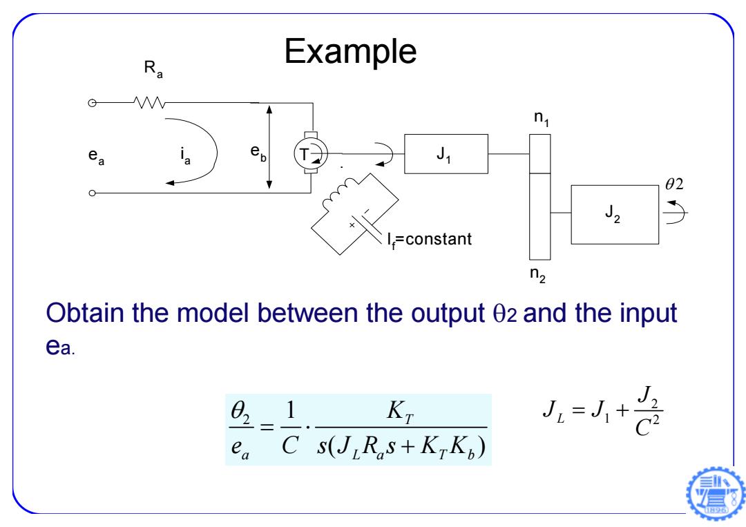
Ra Example G &x J1 02 J2 5 I,=constant n2 Obtain the model between the output 02 and the input ea. 021 K J-+是 ea C s(J Rs+KKp)
Example ea If=constant Ra eb T J1 2 ia n1 n2 J2 Obtain the model between the output 2 and the input ea. 2 1 ( ) T a La T b K e C sJ Rs K K 2 L 1 2 J J J C
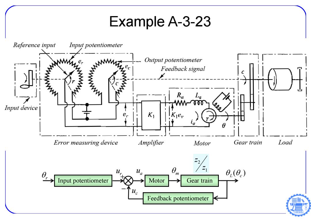
Example A-3-23 Reference input Input potentiometer Output potentiometer Feedback signal Input device Error measuring device Amplifier Motor Gear train Load ur a Z 0(0) Input potentiometer Motor Gear train Feedback potentiometer
Example A-3-23 r r u u c a u m ( ) L c 1 2 z z Input potentiometer Motor Gear train Feedback potentiometer
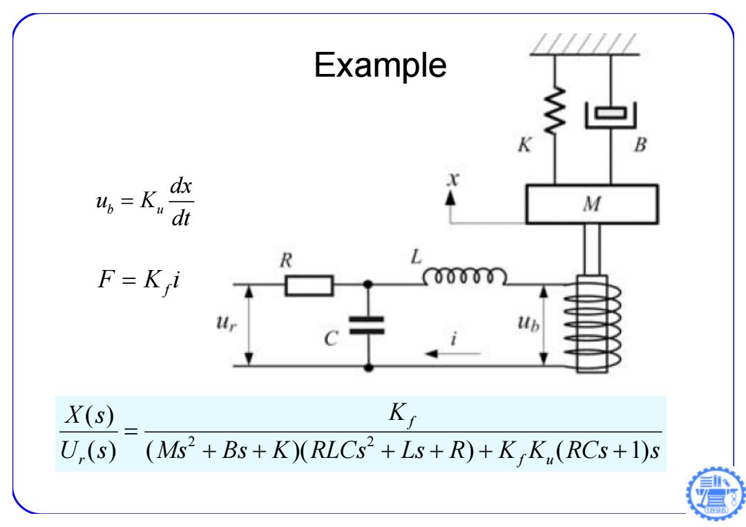
Example K dx 4=K, dt M F=K i 0000n X(s) Ki U.(s) (Ms2+Bs+K)(RLCs2+Ls+R)+KK,(RCs+1)s 日96
Example Ms Bs K RLCs Ls R K K RCs s K U s X s f u f r ( ) ( )( ) ( 1) ( ) 2 2 b u dx u K dt F Ki f