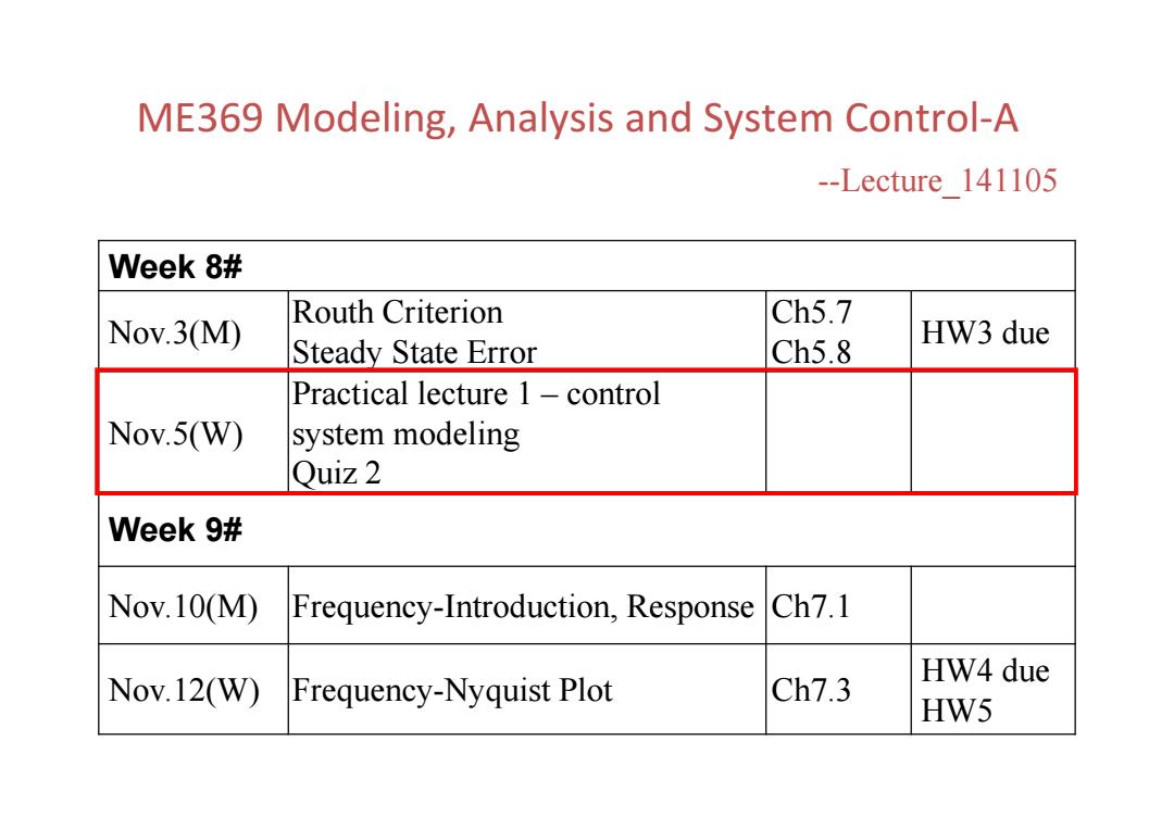
ME369 Modeling,Analysis and System Control-A --Lecture 141105 Week 8# Nov.3(M) Routh Criterion Ch5.7 HW3 due Steady State Error Ch5.8 Practical lecture 1-control Nov.5(W) system modeling Quiz 2 Week 9# Nov.10(M) Frequency-Introduction,Response Ch7.1 Ch7.3 HW4 due Nov.12(W)Frequency-Nyquist Plot HW5
ME369 Modeling, Analysis and System Control‐A --Lecture_141105 Week 8# Nov.3(M) Routh Criterion Steady State Error Ch5.7 Ch5.8 HW3 due Nov.5(W) Practical lecture 1 – control system modeling Quiz 2 Week 9# Nov.10(M) Frequency-Introduction, Response Ch7.1 Nov.12(W) Frequency-Nyquist Plot Ch7.3 HW4 due HW5
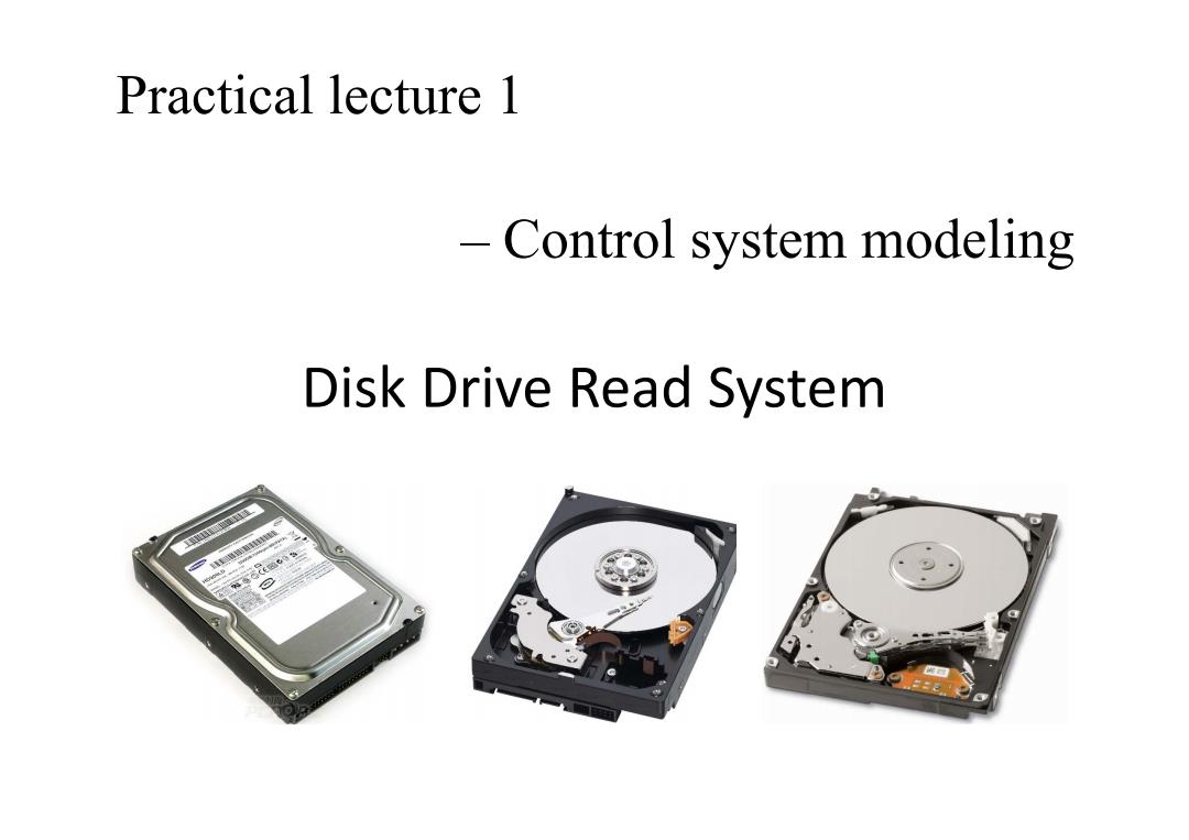
Practical lecture 1 -Control system modeling Disk Drive Read System E
Disk Drive Read System Practical lecture 1 – Control system modeling
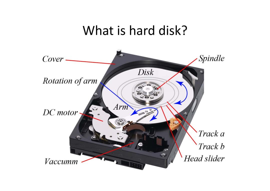
What is hard disk? Cover Spindle Disk Rotation ofarm Arm DC motor- Track a Track b Vaccumm Head slider
What is hard disk?
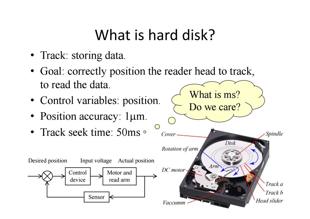
What is hard disk? ·Track:storing data. Goal:correctly position the reader head to track, to read the data. What is ms? Control variables:position. Do we care? Position accuracy:lum. Track seek time:50ms Cover Spindle Disk Rotation of arm Desired position Input voltage Actual position Arm Control Motor and DC motor device read arm Track a Track b Sensor Vaccumm Head slider
What is hard disk? • Track: storing data. • Goal: correctly position the reader head to track, to read the data. • Control variables: position. • Position accuracy: 1m. • Track seek time: 50ms Control device Motor and read arm Sensor Desired position Actual position Input voltage What is ms? Do we care?
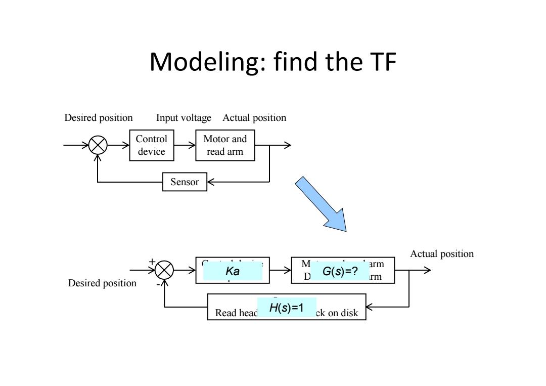
Modeling:find the TF Desired position Input voltage Actual position Control Motor and device read arm Sensor Actual position arm Ka D G(s)=? rm Desired position Read head H(S)=1 ck on disk
Modeling: find the TF Control device Motor and read arm Sensor Desired position Actual position Input voltage Control device Amplifier Motor and read arm DC motor and arm Sensor Read head and index track on disk Desired position Actual position + - Ka H(s)=1 G(s)=?
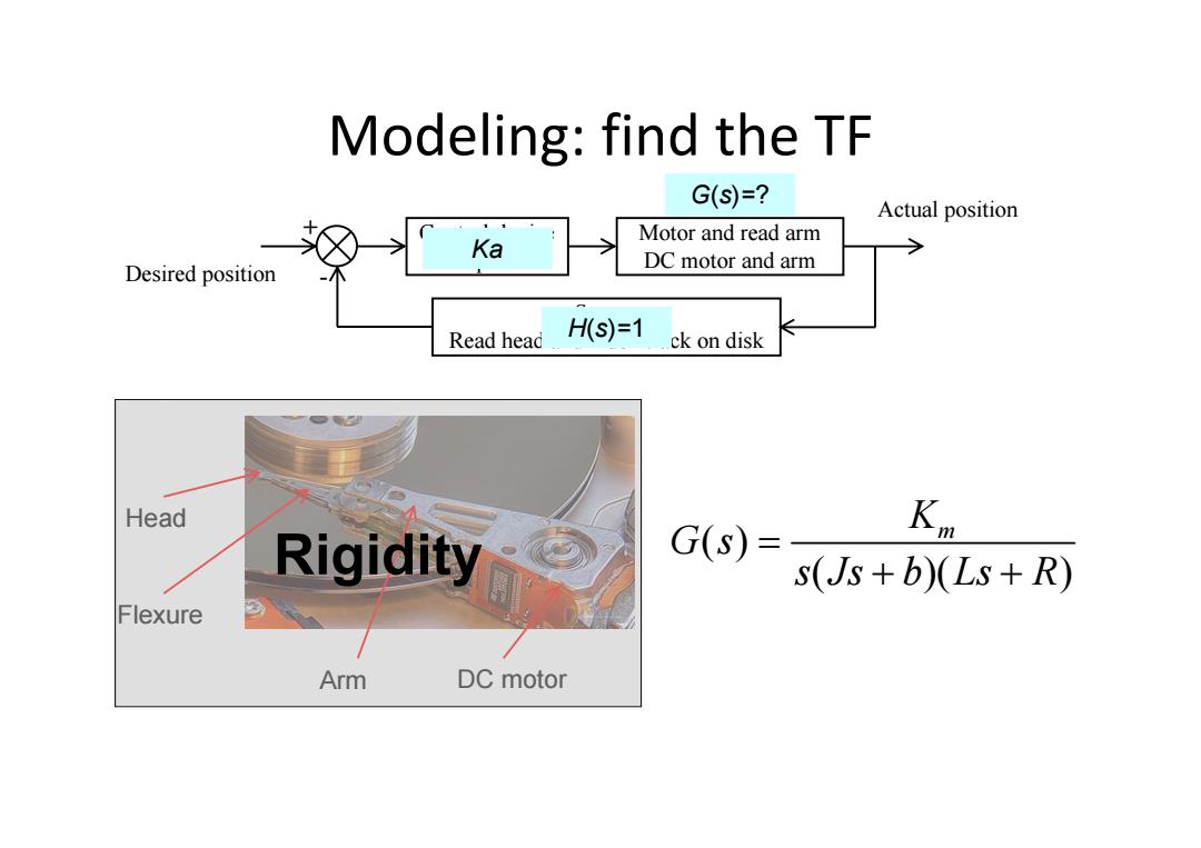
Modeling:find the TF G(S)=? Actual position Motor and read arm Ka Desired position DC motor and arm Read head HS)=1 ck on disk Head G(s) Kn Rigidity s(Js+b)(Ls+R) Flexure Arm DC motor
Modeling: find the TF Control device Amplifier Motor and read arm DC motor and arm Sensor Read head and index track on disk Desired position Actual position + - Ka H(s)=1 G(s)=? Arm DC motor Flexure Head Rigidity ( ) ( )( ) Km G s s Js b Ls R
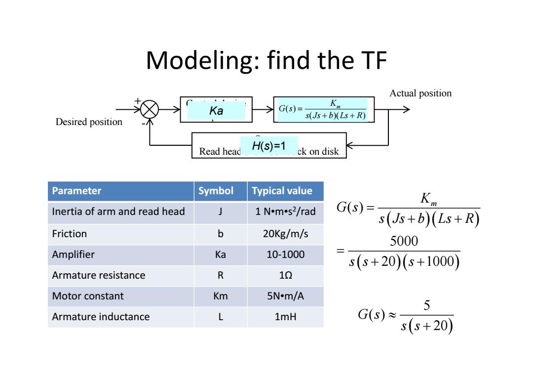
Modeling:find the TF Actual position Ka G(s)= s(Js+b)(Ls+R) Desired position Read head HS)=1 ck on disk Parameter Symbol Typical value Inertia of arm and read head 1 N.m-s2/rad G(s)= (Js+b)(Ls+R) Friction b 20Kg/m/s 5000 Amplifier Ka 10-1000 s(s+20)(s+1000) Armature resistance R 10 Motor constant Km 5N-m/A 5 Armature inductance L 1mH G(s)≈ s(s+20)
Modeling: find the TF Control device Amplifier Motor and read arm DC motor and arm Sensor Read head and index track on disk Desired position Actual position + - Ka H(s)=1 ( ) ( )( ) Km G s s Js b Ls R Parameter Symbol Typical value Inertia of arm and read head J 1 N•m•s2/rad Friction b 20Kg/m/s Amplifier Ka 10‐1000 Armature resistance R 1Ω Motor constant Km 5N•m/A Armature inductance L 1mH ( ) 5000 20 1000 K m G s s Js b Ls R ss s 5 ( ) 20 G s s s
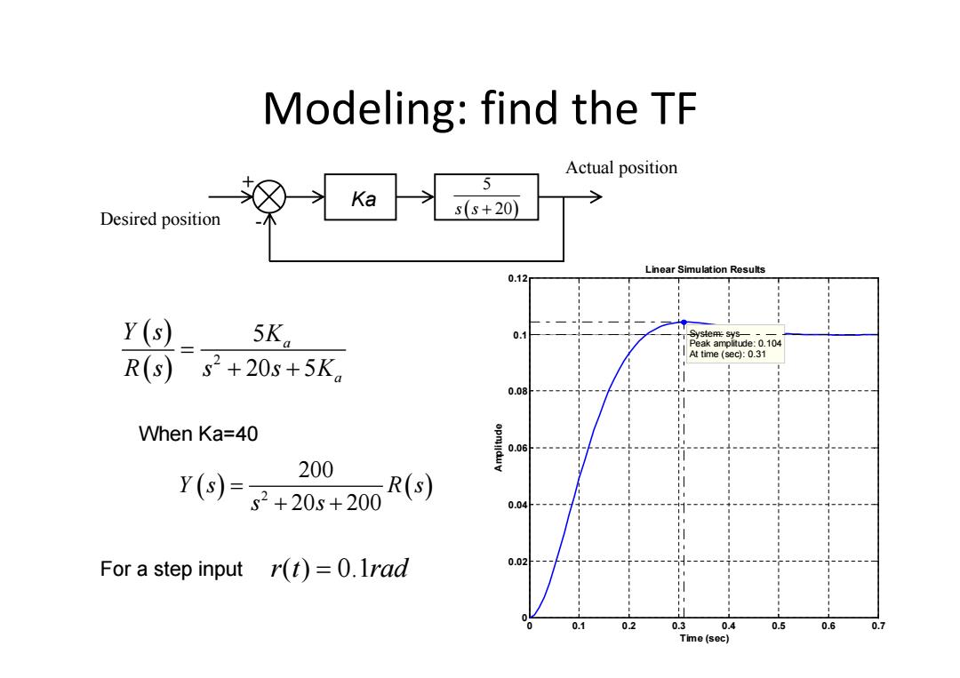
Modeling:find the TF Actual position 5 Ka Desired position s(s+20) Linear Simulation Results 0.12 Y(s) 5Ka 0.1 yeys Peak amolitude:0.104 2+20s+5K。 At time (sec):0.31 R(s)5 0.08 When Ka=40 0.06 200 Y()=子+20s+200 R(s) 0.04 For a step input r(t)=0.1rad 0.02 0.1 0.2 0.3 0.4 0.5 0.6 0.7 Time (sec)
Modeling: find the TF Desired position Actual position + - 5 s s 20 Ka 2 5 20 5 a a Y s K R s s sK When Ka=40 2 200 20 200 Y s Rs s s For a step input r t rad ( ) 0.1 Linear Simulation Results Time (sec) Amplitude 0 0.1 0.2 0.3 0.4 0.5 0.6 0.7 0 0.02 0.04 0.06 0.08 0.1 0.12 System: sys Peak amplitude: 0.104 At time (sec): 0.31
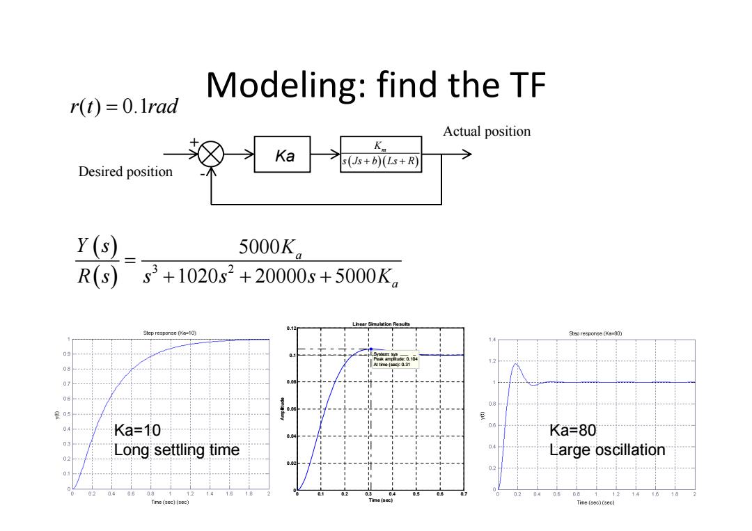
Modeling:find the TF r(t)=0.Irad Actual position Ka Ka s(Js+b)(Ls+R) Desired position Y(s) 5000K R(s) s3+1020s2+20000s+5000K, 212 Step response (Ka-10) Step response (Ka-80) 0.10 0.3 皇05 Ka=10 Ka=80 Long settling time Large oscillation 04 06 06 12 Tme (sec)(sec) Time(sec)(sec)
Modeling: find the TF r t rad ( ) 0.1 Desired position Actual position + - Ka Km s Js b Ls R 3 2 5000 1020 20000 5000 a a Y s K Rs s s s K Linear Simulation Results Time (sec) Amplitude 0 0.1 0.2 0.3 0.4 0.5 0.6 0.7 0 0.02 0.04 0.06 0.08 0.1 0.12 System: sys Peak amplitude: 0.104 At time (sec): 0.31 Ka=10 Long settling time Ka=80 Large oscillation
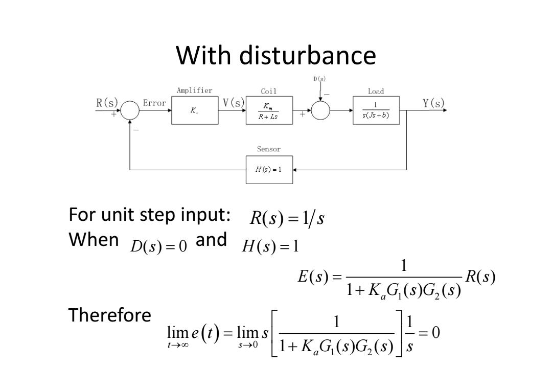
With disturbance D(s) Amplifier Coil Load R(s) Error V(s) K 1 Y(s) R+Ls s(Js+b) Sensor HS)=1 For unit step input: R(s)=1/s When D(s)=0 and H(s)=1 (S 1 R(s) 1+K,G(s)G2(s) Therefore me0=1中ka同
With disturbance For unit step input: When and Therefore Rs s () 1 D s() 0 H s() 1 1 2 1 () () 1 () () a Es Rs KG sG s 0 1 2 1 1 lim lim 0 1 () () t s a et s KG sG s s