实验十VGA彩条信号发生器实验 一、实验目的 1、了解普通显示器正确显示的时序。 2、了解VHDL产生VGA显示时序的方法。 3、进一步加强对FPGA的认识。 二、硬件要求 1、普通显示器一台。 2、FPGA主芯片。 3、12MHz时钟源。 4、按键一个。 三、实验原理 VGA显示器在显示过程中主要由五个信号来控制,分别是R、G、B、HS和VS。其中R、 G、B分别用来驱动显示器三个基色的显示,即红、绿和篮,HS是行同步信号,VS是场同步 信号。在做本实验时,由于没有任何显示器驱动,所以显示器工作在默认状态,分辨率:640 ×480,刷新率:60Hz。在此状态下,当VS和HS都为低电平时,VGA显示器显示亮的状态, 其正向扫描过程约为26us。当一行扫描结束后,行同步信号HS置高电平,持续约6us后, 变成低电平,在HS为高电平期间,显示器产生消隐信号,这就是显示器回扫的过程。当扫 描完一场后,也就是扫描完480行以后,场同步信号VS置高电平,产生场同步,此同步信 号可以使扫描线回到显示器的第一行第一列位置。显示器显示的时序图如下图所示: HS: T1—T2 VS: T4- 上图中T1为同步消隐信号,约为6us脉宽,T2为行显示过程,约为26us,T3为汉同 步信号,宽度为两个行同步周期,T4为显示时间,约为480行周期。 以上就是普通CRT显示器完整显示一屏的时序图。 四、实验内容及步骤 本实验实现的功能是模拟CT显示器的工作时序,通过按键控制,能在屏幕上显示一些 花样的彩条信号来。实验步骤如下: 1、编写CRT显示时序的HDL代码。 2、用QuartusII对其进行编译仿真 3、在时序确定无误后,选择芯片ACEX1KEP1K10TC100一3。 4、给芯片进行管脚绑定,在此进行编译。 5、根据自己绑定的管脚,在实验箱上对VGA借口和FPGA之间进行正确连线。 6、给目标板下载代码,按下按键,观看实验结果。 五、实验连线
实验十 VGA 彩条信号发生器实验 一、实验目的 1、 了解普通显示器正确显示的时序。 2、 了解 VHDL 产生 VGA 显示时序的方法。 3、 进一步加强对 FPGA 的认识。 二、硬件要求 1、 普通显示器一台。 2、 FPGA 主芯片。 3、 12MHz 时钟源。 4、 按键一个。 三、实验原理 VGA 显示器在显示过程中主要由五个信号来控制,分别是 R、G、B、HS 和 VS。其中 R、 G、B 分别用来驱动显示器三个基色的显示,即红、绿和篮,HS 是行同步信号,VS 是场同步 信号。在做本实验时,由于没有任何显示器驱动,所以显示器工作在默认状态,分辨率:640 ×480,刷新率:60Hz。在此状态下,当 VS 和 HS 都为低电平时,VGA 显示器显示亮的状态, 其正向扫描过程约为 26us。当一行扫描结束后,行同步信号 HS 置高电平,持续约 6us 后, 变成低电平,在 HS 为高电平期间,显示器产生消隐信号,这就是显示器回扫的过程。当扫 描完一场后,也就是扫描完 480 行以后,场同步信号 VS 置高电平,产生场同步,此同步信 号可以使扫描线回到显示器的第一行第一列位置。显示器显示的时序图如下图所示: 上图中 T1 为同步消隐信号,约为 6us 脉宽,T2 为行显示过程,约为 26us,T3 为汉同 步信号,宽度为两个行同步周期,T4 为显示时间,约为 480 行周期。 以上就是普通 CRT 显示器完整显示一屏的时序图。 四、实验内容及步骤 本实验实现的功能是模拟 CRT 显示器的工作时序,通过按键控制,能在屏幕上显示一些 花样的彩条信号来。实验步骤如下: 1、编写 CRT 显示时序的 VHDL 代码。 2、用 QuartusII 对其进行编译仿真。 3、在时序确定无误后,选择芯片 ACEX1K EP1K10TC100-3。 4、给芯片进行管脚绑定,在此进行编译。 5、根据自己绑定的管脚,在实验箱上对 VGA 借口和 FPGA 之间进行正确连线。 6、给目标板下载代码,按下按键,观看实验结果。 五、实验连线

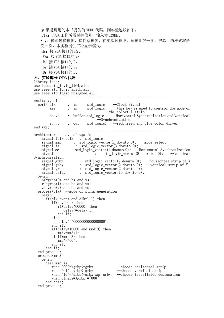
如果是调用的本书提供的VDL代码,则实验连线如下: C1k:FPGA工作所需时钟信号,输入为12Mz。 Ky:模式选择按键,接任意按键,在实验过程中,每按此键一次,屏幕上的样式将改 变一次,本实验提供三种显示模式。 Hs:接VGA接口的HS。 Vs:接VGA接▣的VS R:接VGA接口的R。 G:接VGA接口的G。 B:接VGA接口的B。 六、实验部分DL代码 library ieee; use ieee.std_logic_1164.all; use ieee.std_logic_arith.all: use ieee.std_logic_unsigned.all; entity vga is port(clk in std logic; -Clock Signal key in std logic; -this key is used to control the mode of --the colorful strip hs,vs buffer std_logic: --Horizontal Synchronization and Vertical --Synchronization r,g,b out std logic); -red,green and blue color dirver end vga: architecture behave of vga is signal fclk,cclk std logic; signal mmd std logic vector(1 downto 0); --mode select signal fs std logic vector(3 downto 0); signal cc std logic vector(4 downto 0); --Horizontal Synchronization signal ll 。 std logic vector(8 downto 0): --Vertical Synchronization signal grbx std logic vector(2 downto 0); --horizontal strip of X signal grby std logic_vector(2 downto 0); --vertical strip of Y signal grbp std logic vector(2 downto 0); signal delay std_logic_vector(15 downto 0); begin bgrbpgrbpgrbpgrbp<="000": end case; end process;
如果是调用的本书提供的 VHDL 代码,则实验连线如下: Clk:FPGA 工作所需时钟信号,输入为 12MHz。 Key:模式选择按键,接任意按键,在实验过程中,每按此键一次,屏幕上的样式将改 变一次,本实验提供三种显示模式。 Hs:接 VGA 接口的 HS。 Vs:接 VGA 接口的 VS。 R:接 VGA 接口的 R。 G:接 VGA 接口的 G。 B:接 VGA 接口的 B。 六、实验部分 VHDL 代码 library ieee; use ieee.std_logic_1164.all; use ieee.std_logic_arith.all; use ieee.std_logic_unsigned.all; -------------------------------------------------------------------- entity vga is port( clk : in std_logic; --Clock Signal key : in std_logic; --this key is used to control the mode of --the colorful strip hs,vs : buffer std_logic; --Horizontal Synchronization and Vertical --Synchronization r,g,b : out std_logic); --red,green and blue color dirver end vga; -------------------------------------------------------------------- architecture behave of vga is signal fclk,cclk : std_logic; signal mmd : std_logic_vector(1 downto 0); --mode select signal fs : std_logic_vector(3 downto 0); signal cc : std_logic_vector(4 downto 0); --Horizontal Synchronization signal ll : std_logic_vector(8 downto 0); --Vertical Synchronization signal grbx : std_logic_vector(2 downto 0); --horizontal strip of X signal grby : std_logic_vector(2 downto 0); --vertical strip of Y signal grbp : std_logic_vector(2 downto 0); signal delay : std_logic_vector(15 downto 0); begin bgrbpgrbpgrbpgrbp<="000"; end case; end process;

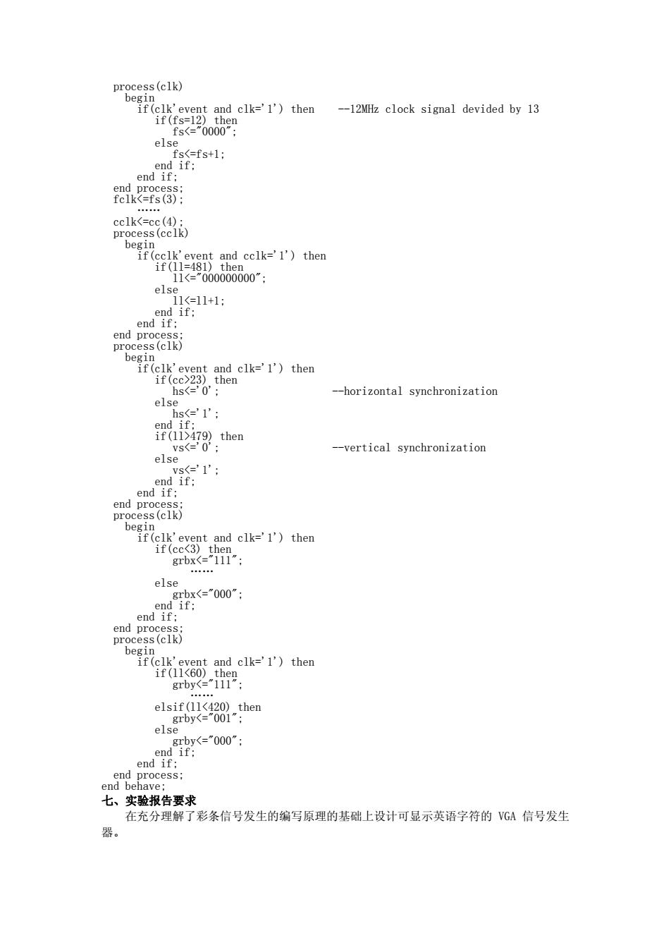
process(clk) begin if(clk'event and clk='1')then -12MHz clock signal devided by 13 if(fs=12)then fs23)then hs479)then vs=0; --vertical synchronization else vs<e'1'; end if; end if; end process: process(clk) begin if(clk'event and clk='1')then if(cc<3)then grbx<="111”: ee中。 else grbx<="000”: end if; end if; end process: process(clk) begin if(clk'event and clk='1')then if(11<60)then grby<="111": elsif(11<420)then grby<="001"; els grby<="000": end if: end if; end process; end behave; 七、实验报告要求 在充分理解了彩条信号发生的编写原理的基础上设计可显示英语字符的VGA信号发生 器
process(clk) begin if(clk'event and clk='1') then --12MHz clock signal devided by 13 if(fs=12) then fs23) then hs479) then vs<='0'; --vertical synchronization else vs<='1'; end if; end if; end process; process(clk) begin if(clk'event and clk='1') then if(cc<3) then grbx<="111"; …… else grbx<="000"; end if; end if; end process; process(clk) begin if(clk'event and clk='1') then if(ll<60) then grby<="111"; …… elsif(ll<420) then grby<="001"; else grby<="000"; end if; end if; end process; end behave; 七、实验报告要求 在充分理解了彩条信号发生的编写原理的基础上设计可显示英语字符的 VGA 信号发生 器