实验十二 电梯控制实验 一、实验目的 1、了解电梯时序电路的实现。 2、掌握用FPGA实现电梯模型的方法。 3、体验FPGA的多用途性。 二、硬件要求 1、电梯模块。 2、点阵模块。 3、750KHz时钟源。 4、主芯片FPGA EP1K10TC100一3。 三、实验原理 本实验是用FPGA来实现一个三层楼的电梯模型,并利用点阵显示电梯当前所在楼层。 点阵显示与七段码显示原理相同,也是通过扫描来显示。下面主要讲一下电梯实现过程中的 几个主要部分。 楼层到楼层之间的间隔:用计数器来实现。 开门与关门之间的间隔:用计数器来实现。 电梯向上还是向下:如果现在电梯在1楼,肯定以后向上走:如果现在在三楼,那么 以后肯定向下:如果现在电梯在2楼,如果现在电梯向下开,且1楼有人按键,那么不管三 楼有没有人按钮,则先到1楼:如果现在电梯向上开,且3楼有人按钮,则不管1楼有没有 人呼叫,一直开到3楼:如果电梯现在在2楼,且处于向下开到状态,但是1楼没有按钮, 那么如果这个时候要是3楼有人呼叫,就向上开,反之,则向下开。 至于显示部分,则只根据当前电梯所在的位置来确定,与电梯的运行方向无关。 四、实验内容及步骤 本实验需要完成的任务是编写DL代码来模拟现实中的三层电梯工作。在点阵上显示 电梯所在的楼层,当其它楼层有上或下的请求信号时,表示该楼层上或下的绿色或黄色指示 灯亮,电梯开始上或下运行,当到达该楼层时,表示该楼层上或下的绿色或黄色指示灯灭, 表示到达该楼层的红色指示灯亮,点阵显示楼层数,红色指示灯灭。实验步骤如下: 1、编写电梯的VDL代码。 2、用QuartusII对其进行编译仿真。 3、在仿真确定无误后,选择芯片ACEX1KEP1K10TC100一3。 4、给芯片进行管脚绑定,再此进行编译。 5、根据自己绑定的管脚,在实验箱上对步进电机和FPGA之间进行正确连线。 6、给目标板下载代码,按下楼层上、下键,观看实验结果。 五、实验连线 如果是调用的本书提供的DL代码,则实验连线如下: C1k:FPGA工作所需时钟信号,输入为750Hz。 K1、k2u、k2d、k3:分别接电梯模型的1KU、2KU、2KD和3K①。 D1、d2u、d2d、d3:分别接电梯模型的1U、2U、2D和3D。 door1、door2、door3:分别与电梯模块的1D00R、2D00R和3D00R相连。 R0、r1、r2、r3、r4、r5、r6、r7:分别与点阵显示的ROW0、ROW1、R0W2、ROW3、ROW4、 ROW5、ROW6和ROW7相连。 Sa、Sb、Sc:分别与点阵显示的sel0、sel1和sel3相连。 六、实验部分HDL代码 library ieee:
实验十二 电梯控制实验 一、实验目的 1、 了解电梯时序电路的实现。 2、 掌握用 FPGA 实现电梯模型的方法。 3、 体验 FPGA 的多用途性。 二、硬件要求 1、 电梯模块。 2、 点阵模块。 3、 750KHz 时钟源。 4、 主芯片 FPGA EP1K10TC100—3。 三、实验原理 本实验是用 FPGA 来实现一个三层楼的电梯模型,并利用点阵显示电梯当前所在楼层。 点阵显示与七段码显示原理相同,也是通过扫描来显示。下面主要讲一下电梯实现过程中的 几个主要部分。 楼层到楼层之间的间隔:用计数器来实现。 开门与关门之间的间隔:用计数器来实现。 电梯向上还是向下:如果现在电梯在 1 楼,肯定以后向上走;如果现在在三楼,那么 以后肯定向下;如果现在电梯在 2 楼,如果现在电梯向下开,且 1 楼有人按键,那么不管三 楼有没有人按钮,则先到 1 楼;如果现在电梯向上开,且 3 楼有人按钮,则不管 1 楼有没有 人呼叫,一直开到 3 楼;如果电梯现在在 2 楼,且处于向下开到状态,但是 1 楼没有按钮, 那么如果这个时候要是 3 楼有人呼叫,就向上开,反之,则向下开。 至于显示部分,则只根据当前电梯所在的位置来确定,与电梯的运行方向无关。 四、实验内容及步骤 本实验需要完成的任务是编写 VHDL 代码来模拟现实中的三层电梯工作。在点阵上显示 电梯所在的楼层,当其它楼层有上或下的请求信号时,表示该楼层上或下的绿色或黄色指示 灯亮,电梯开始上或下运行,当到达该楼层时,表示该楼层上或下的绿色或黄色指示灯灭, 表示到达该楼层的红色指示灯亮,点阵显示楼层数,红色指示灯灭。实验步骤如下: 1、编写电梯的 VHDL 代码。 2、用 QuartusII 对其进行编译仿真。 3、在仿真确定无误后,选择芯片 ACEX1K EP1K10TC100-3。 4、给芯片进行管脚绑定,再此进行编译。 5、根据自己绑定的管脚,在实验箱上对步进电机和 FPGA 之间进行正确连线。 6、给目标板下载代码,按下楼层上、下键,观看实验结果。 五、实验连线 如果是调用的本书提供的 VHDL 代码,则实验连线如下: Clk:FPGA 工作所需时钟信号,输入为 750Hz。 K1、k2u、k2d、k3:分别接电梯模型的 1KU、2KU、2KD 和 3KD。 D1、d2u、d2d、d3:分别接电梯模型的 1U、2U、2D 和 3D。 door1、door2、door3:分别与电梯模块的 1DOOR、2DOOR 和 3DOOR 相连。 R0、r1、r2、r3、r4、r5、r6、r7:分别与点阵显示的 ROW0、ROW1、ROW2、ROW3、ROW4、 ROW5、ROW6 和 ROW7 相连。 Sa、Sb、Sc:分别与点阵显示的 sel0、sel1 和 sel3 相连。 六、实验部分 VHDL 代码 library ieee;

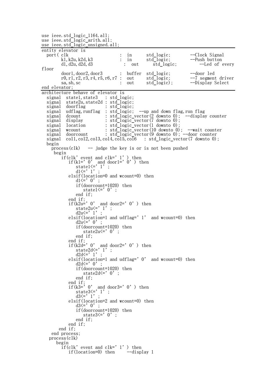
use ieee.std logic 1164.all; use ieee.std_logic_arith.all: use ieee.std_logic_unsigned.all; entity elevator is port(clk in std logic; --Clock Signal k1,k2u,k2d,k3 in std_logic: --Push button d1,d2u,d2d,d3 out std logic; --Led of every floor door1,door2,door3 buffer std logic: --door led r0,r1,r2,r3,r4,r5,r6,r7: out std logic; --7 segment driver sa,sb,sc out std logic); -Display Select end elevator; architecture behave of elevator is signal statel,state3 std logic: signal state2u,state2d std logic; signal doorflag std logic: signal udflag,runflag std logic; --up and down flag,run flag signal dcount std_logic_vector(2 downto 0): --display counter signal display std logic vector(7 downto 0); signal location std_logic_vector(1 downto 0); signal wcount std logic vector(10 downto 0); --wait counter signal doorcount std-logic_vector(9 downto 0):--door counter signal col1,col2,col3,col4,col5,col6 std_logic_vector(7 downto 0); begin process(clk) judge the key is or is not been pushed begin if(clk'event and clk='1')then if (kl=0 and door1='0')then statel<='1'; d1<=’1’: elsif(location=0 and wcount=0)then de’0': if(doorcount=1020)then statel<='0' end if; end if; if(k2u='0'and door2='0')then state2u<=' 1 d2u<=’1 elsif(location=1 and udflag='1'and wcount=0)then d2u<= 0 if(doorcount=1020)then state2u<='0': end if; end if; if(k2d=’0' and door2='0')then state2d<=’I d2d=1 elsif(location=1 and udflag='0'and wcount=0)then d2d<=’0': if(doorcount=1020)then state2d<='0'; end if; end if; if(k3=0'and door3='0')then state3<=’1' d3<= 1 elsif(location=2 and wcount=0)then d3<=0': if(doorcount=1020)then state:3<=’0': end if; end if; end if; end process; process(clk) begin if(clk'event and clk='1')then if(location=0)then --display 1
use ieee.std_logic_1164.all; use ieee.std_logic_arith.all; use ieee.std_logic_unsigned.all; entity elevator is port( clk : in std_logic; --Clock Signal k1,k2u,k2d,k3 : in std_logic; --Push button d1,d2u,d2d,d3 : out std_logic; --Led of every floor door1,door2,door3 : buffer std_logic; --door led r0,r1,r2,r3,r4,r5,r6,r7 : out std_logic; --7 segment driver sa,sb,sc : out std_logic); --Display Select end elevator; architecture behave of elevator is signal state1,state3 : std_logic; signal state2u,state2d : std_logic; signal doorflag : std_logic; signal udflag,runflag : std_logic; --up and down flag,run flag signal dcount : std_logic_vector(2 downto 0); --display counter signal display : std_logic_vector(7 downto 0); signal location : std_logic_vector(1 downto 0); signal wcount : std_logic_vector(10 downto 0); --wait counter signal doorcount : std_logic_vector(9 downto 0); --door counter signal col1,col2,col3,col4,col5,col6 : std_logic_vector(7 downto 0); begin process(clk) -- judge the key is or is not been pushed begin if(clk’event and clk=’1’) then if(k1=’0’ and door1=’0’) then state1<=’1’; d1<=’1’; elsif(location=0 and wcount=0) then d1<=’0’; if(doorcount=1020) then state1<=’0’; end if; end if; if(k2u=’0’ and door2=’0’) then state2u<=’1’; d2u<=’1’; elsif(location=1 and udflag=’1’ and wcount=0) then d2u<=’0’; if(doorcount=1020) then state2u<=’0’; end if; end if; if(k2d=’0’ and door2=’0’) then state2d<=’1’; d2d<=’1’; elsif(location=1 and udflag=’0’ and wcount=0) then d2d<=’0’; if(doorcount=1020) then state2d<=’0’; end if; end if; if(k3=’0’ and door3=’0’) then state3<=’1’; d3<=’1’; elsif(location=2 and wcount=0) then d3<=’0’; if(doorcount=1020) then state3<=’0’; end if; end if; end if; end process; process(clk) begin if(clk’event and clk=’1’) then if(location=0) then --display 1

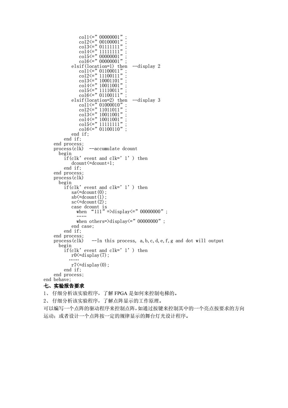
co11display<=”00000000”: end case; end if; end process; process(clk) --In this process,a,b,c,d,e,f,g and dot will output begin if(clk'event and clk='1')then r0<=display(7); r7<=display(0); end if; end process; end behave; 七、实验报告要求 1、仔细分析该实验程序,了解FPGA是如何来控制电梯的。 2、仔细分析该实验程序,了解点阵显示的工作原理。 可以编写一个点阵的驱动程序来控制点阵,如通过按键来控制其中的一个亮点按要求的方向 运动:或者设计一个点阵按一定的规律显示的舞台灯光设计程序
col1displaydisplay<=”00000000”; end case; end if; end process; process(clk) --In this process, a,b,c,d,e,f,g and dot will output begin if(clk’event and clk=’1’) then r0<=display(7); …… r7<=display(0); end if; end process; end behave; 七、实验报告要求 1、 仔细分析该实验程序,了解 FPGA 是如何来控制电梯的。 2、 仔细分析该实验程序,了解点阵显示的工作原理。 可以编写一个点阵的驱动程序来控制点阵,如通过按键来控制其中的一个亮点按要求的方向 运动;或者设计一个点阵按一定的规律显示的舞台灯光设计程序