电路学习指导 第三章电阻电路的一般分析 CAPTER5 OPERATIONALAMPLIFIER 5-1 Introduction The operational amplifier, or amp for shot is an electronic unit that behaves like a voltage controlled voltage source. It can also be regarded as a voltage amplifier with very high gain. An op amp can sum signals, amplify a signal, integrate it,or differentiate it. That is why it is called an operational amplifier.5-2 The circuit symbol and equivalent circuit The circuit symbol is shown as Fig.5-1.The inputs are marked with minus(-)and plus(+)to specify inverting and non-inverting inputs, respectively inverting 5-2. The autut u in aivan huA in the nan ln 0 input u=(-)output + R。 + VC noninverting oionship lir inputo+ ud Aud u, + R 12 。 Fig.5-1 Fig.5-2 uo positive saturation uco 20K.∩ linear region 10K 5-3 1 + 741 T 0 u:quiva + A=0.2negative initive us nd 0 uo/us=saturation 10Kn >11 20KΩ ud +° + + R。 + →12 十 ud Aud u。 u。 + R 士 。 ÷ Fig.5-5 Fig.5-6 Although assuming an ideal op amp provides only an approximate analysis, most modern amplifiers have such large gains and input impedances that the approximate analysis is a good one. The two important characteristics of the ideal op amp are: 1 The currents into both input terminals are zeros:i1=0,i2=0.This is due to the infinite inpute resistance. 2 The voltage across the input terminals is negligibly small;That is ud=ul-u2=0(Because uo=Aud=finite, A is infinite,ud is infinitely small or infinitesimal) Some op amp circuit: 21
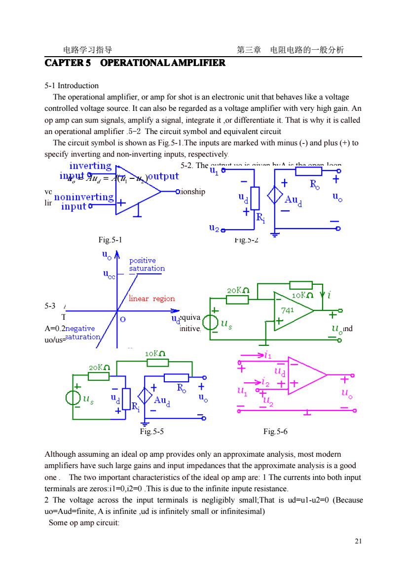
电路学习指导 第三章 电阻电路的一般分析 21 CAPTER 5 OPERATIONAL OPERATIONAL OPERATIONAL OPERATIONALAMPLIFIER AMPLIFIER AMPLIFIER AMPLIFIER 5-1 Introduction The operational amplifier, or amp for shot is an electronic unit that behaves like a voltage controlled voltage source. It can also be regarded as a voltage amplifier with very high gain. An op amp can sum signals, amplify a signal, integrate it ,or differentiate it. That is why it is called an operational amplifier .5-2 The circuit symbol and equivalent circuit The circuit symbol is shown as Fig.5-1.The inputs are marked with minus (-) and plus (+) to specify inverting and non-inverting inputs, respectively. The equivalent circuit is shown as Fig.5-2. The output uo is given byA is the open-loop voltage gainThe current and voltage relationship is shown as Fig.5-3, op amp operate in linear region Fig.5-1 Fig.5-2 5-3 A proportional circuit The circuit is shown as Fig.5-4, Its equivalent circuit is Fig.5-5.When A=0.2M,u0/us=-1.9999699When A= infinitive, Ri= infinitive, Ro=0, it is a ideal op amp,and uo/us=2.The error is very small Fig.5-5 Fig.5-6 Although assuming an ideal op amp provides only an approximate analysis, most modern amplifiers have such large gains and input impedances that the approximate analysis is a good one . The two important characteristics of the ideal op amp are: 1 The currents into both input terminals are zeros:i1=0,i2=0 .This is due to the infinite inpute resistance. 2 The voltage across the input terminals is negligibly small;That is ud=u1-u2=0 (Because uo=Aud=finite, A is infinite ,ud is infinitely small or infinitesimal) Some op amp circuit: ( ) uo = Aud = A u1 − u2
电路学习指导 第三章电阻电路的一般分析 1 Inverting amplifier,the noninverting is grounded. 2 noninverting amplifier summing amplifier 4 integrator 5 differentiator 6 the follower Solution First=i 2-Doo R Thus-=∥- Fig.E5-1 Second because so Solution Method 1 using nodal analysis Becausei=i=0,ua=ub To nodea and b,the nodal equations are t在 a: 龙元尼w党 b: 发+龙号 Fig.E5-2 咖s竞党+党·or%=是-/ Method2 Because=t = R R R 22
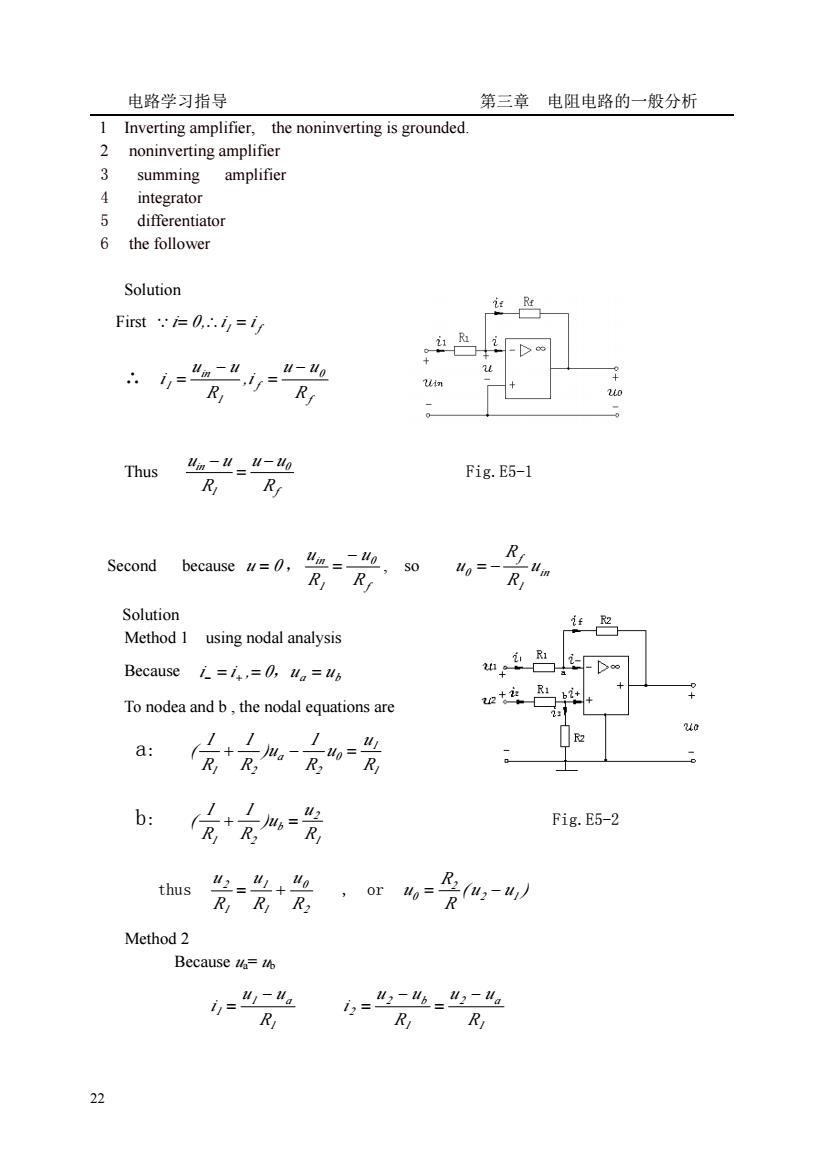
电路学习指导 第三章 电阻电路的一般分析 22 1 Inverting amplifier, the noninverting is grounded. 2 noninverting amplifier 3 summing amplifier 4 integrator 5 differentiator 6 the follower Solution First 1 f ∵i= 0,∴i = i ∴ f 0 f 1 in 1 R u u ,i R u u i − = − = Thus f 0 1 in R u u R u u − = − Fig.E5-1 Second because u = 0 , f 0 1 in R u R u − = , so in 1 f 0 u R R u = − Solution Method 1 using nodal analysis Because 0 u a ub i − = i + ,= , = To nodea and b , the nodal equations are a: 1 1 0 2 a 1 2 R u u R 1 )u R 1 R 1 ( + − = b: 1 2 b 1 2 R u )u R 1 R 1 ( + = Fig.E5-2 thus 2 0 1 1 1 2 R u R u R u = + , or ( u u ) R R u 2 1 2 0 = − Method 2 Because ua= ub 1 1 a 1 R u u i − = 1 2 a 1 2 b 2 R u u R u u i − = − =
电路学习指导 第三章电阻电路的一般分析 与=%出 and that is ii we get 4-uu=Ma that is R,R2 名泥 and in-i we get 党 R thus (,-W Ho-Ry E5-3 The circuit is shown as Fig.E5-2,determine=?WhereR=R. Solution We use nodal analysis. At node 1 n(D Fig.5-3 Because=0the above equation can be rewritten as ① Because=0 the above equation can be rewritten as
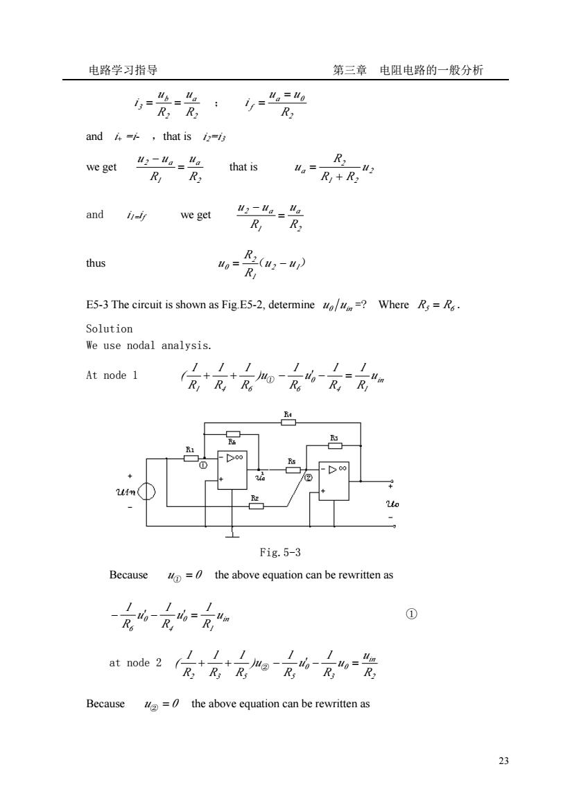
电路学习指导 第三章 电阻电路的一般分析 23 2 a 2 b 3 R u R u i = = ; 2 a 0 f R u u i = = and i+ =i- ,that is i2=i3 we get 2 a 1 2 a R u R u u = − that is 2 1 2 2 a u R R R u + = and i1=if we get 2 a 1 2 a R u R u u = − thus ( 2 1) 1 2 0 u u R R u = − E5-3 The circuit is shown as Fig.E5-2, determine u 0 u in =? Where R5 = R6 . Solution We use nodal analysis. At node 1 in 4 1 0 1 4 6 6 u R 1 R 1 u R 1 )u R 1 R 1 R 1 ( + + ① − ′ − = Fig.5-3 Because u① = 0 the above equation can be rewritten as in 1 0 4 0 6 u R 1 u R 1 u R 1 − ′ − ′ = ① at node 2 2 in 0 3 0 2 3 5 5 R u u R 1 u R 1 )u R 1 R 1 R 1 ( + + ② − ′ − = Because u② = 0 the above equation can be rewritten as
电路学习指导 第三章电阻电路的一般分析 ② From equation①and②we get And G=! The answer is uo G)-G2 uin G3-G Solution Because=0.0 According to the voltage division R R and=up=u so=2ui Usin g superposition when o=0 哈=14足 e= R: Fig.E5-4 4=0 0= m=-=-2 R 24
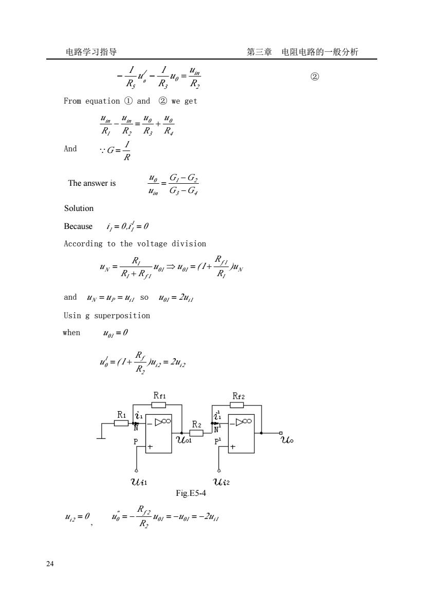
电路学习指导 第三章 电阻电路的一般分析 24 2 in 0 3 / 5 R u u R 1 u R 1 0 − − = ② From equation ① and ② we get And R 1 G R u R u R u R u 4 0 3 0 2 in 1 in = − = + ∵ The answer is 3 4 1 2 in 0 G G G G u u − − = Solution Because i 0,i 0 1 1 = 1 = According to the voltage division N 1 f 1 01 01 1 f 1 1 N )u R R u u (1 R R R u ⇒ = + + = and u N = u P = ui1 so u01 = 2ui1 Usin g superposition when u01 = 0 i2 i2 2 1 f 0 )u 2u R R u = (1 + = Fig.E5-4 u 0 i2 = , 01 01 i1 2 " f 2 0 u u 2u R R u = − = − = −
电路学习 般分析 when and u act together o=%+i%=242-2/=22-41 So:uo=2u-ul) 5-8 Problems P5-1 Draw the circuits when their relationships between andare: 2)=1(3)=10 (4) -=20 +2+ P5-2 The circuit is shown as Fig.P5-2,determine the output voltage ,where R=1,4=2,=-3 P5-3 The circuit is shown as Fig.P5-3,determine the current I. Fig P5-2 Fig.P5-3 P5-4 Determine R R in Fig.P5-4.where=/040 P5-5 In Fig.P5-5,determine the relationship between u andto Fig P5-4 Fig.P5-5
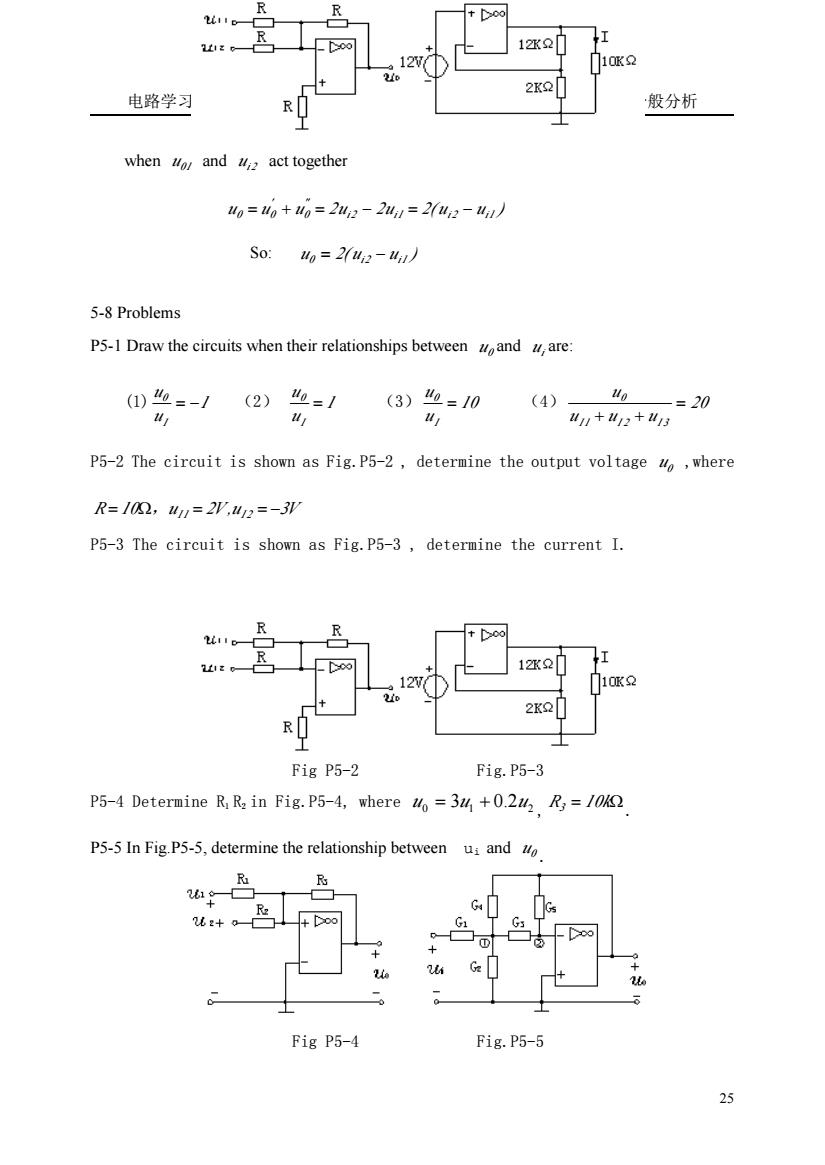
电路学习指导 第三章 电阻电路的一般分析 25 when 01 u and i2 u act together u u u 2u 2u 2( u u ) i2 i1 i2 i1 "0 ' 0 = 0 + = − = − So: u 2( u u ) 0 = i2 − i1 5-8 Problems P5-1 Draw the circuits when their relationships between u0 and ui are: (1) 1 u u I 0 = − (2) 1 u u I 0 = (3) 10 u u I 0 = (4) 20 u u u u I 1 I 2 I 3 0 = + + P5-2 The circuit is shown as Fig.P5-2 , determine the output voltage u 0 ,where R = 10Ω,u I1 = 2V ,u I 2 = −3V P5-3 The circuit is shown as Fig.P5-3 , determine the current I. Fig P5-2 Fig.P5-3 P5-4 Determine R1 R2 in Fig.P5-4, where 0 1 2 2 u = 3u + 0. u , R3 = 10kΩ . P5-5 In Fig.P5-5, determine the relationship between ui and u 0 . Fig P5-4 Fig.P5-5

电路学习指导 第三章电阻电路的一般分析 P5-6 Determine the output voltage o in Fig.P5-6,where RR=R=R/0=10V. m=20V P5-7The circuit is shown as Fig.P5-7,determine Uo/Us Fig P5-6 Fig.P5-7 P5-8 Determine the current I in Fig.P5-8. 26
电路学习指导 第三章 电阻电路的一般分析 26 P5-6 Determine the output voltage u0 in Fig.P5-6 , where R1=R2=R3=R4 =10KΩ,uI1=10V, uI2=20V. P5-7 The circuit is shown as Fig.P5-7 , determine U0/ US . Fig P5-6 Fig.P5-7 P5-8 Determine the 6 V 1 0 K Ω 2 K Ω 1 2 K Ω 0 0 0 0 0 I current I in Fig.P5-8