电路学习指导 第三章电阻电路的一般分析 CAPTER3 THE SYSTEM ANALYSIS OF RESISTANCE CIRCUIT Having understood the fundamental laws of circuit theory, we are now prepared to apply these laws to develop two powerful techniques for circuit analysis: nodal analysis, which is based on a systematic application of KCL, and mesh analysis, which is based on a systematic application of KVL. The two techniques are so important that this chapter should be regarded as the most important in the book. Students are therefore encouraged to pay careful attention. 3-1Nodal Analysis Nodal analysis provides a general procedure for analyzing circuits using node voltages (the voltage from the independent node to the reference node or ground)as the circuit variables. The general form of the nodal equations: G11un1+ G12un1+ G13un3+ ..+ G1nunn=is11 G21un1+ G22un2+ G23un3+ .+ G2nunn=is11 Gnlun1+ Gn2un2+ Gn3un3+ .+ Gnnunn=isnn Where Gkk is the sum of the conductances connected to node k( it is called the self-conductance of node k); Gkj=Gjk is the negative of the sum of the conductances connected between node k and node j(it is called the mutual-conductance of node k and node j); Unk is unknown voltage at node k (nodal voltage); iskk is the sum of all independent current sources directly connected to node k, with currents entering the node treated as positive. Nodal analysis with voltage sources. Case 1: If a voltage source is connected between the nonreference node and a ground, we simply set the this nodal voltage equal to the voltage source Case 2: If the voltage source is connected between two independent nodes, we can suppose a current I flow through the voltage source and treat I as current source with value I. Write the nodal equations, and at last, give a supplementary equation of the voltage source expressed in terms of nodal voltages. 21
电路学习指导 第三章 电阻电路的一般分析 21 CAPTER 3 THE SYSTEM ANALYSIS ANALYSIS ANALYSIS ANALYSIS OF RESISTANCE RESISTANCE RESISTANCE RESISTANCE CIRCUIT CIRCUIT CIRCUIT CIRCUIT Having understood the fundamental laws of circuit theory , we are now prepared to apply these laws to develop two powerful techniques for circuit analysis : nodal analysis , which is based on a systematic application of KCL , and mesh analysis, which is based on a systematic application of KVL . The two techniques are so important that this chapter should be regarded as the most important in the book. Students are therefore encouraged to pay careful attention. 3-1Nodal Analysis Nodal analysis provides a general procedure for analyzing circuits using node voltages ( the voltage from the independent node to the reference node or ground ) as the circuit variables. The general form of the nodal equations: G11un1+ G12un1+ G13un3+ . + G1nunn=iS11 G21un1+ G22un2+ G23un3+ . + G2nunn=iS11 . (3-1) Gn1un1+ Gn2un2+ Gn3un3+ . + Gnnunn=iSnn Where Gkk is the sum of the conductances connected to node k ( it is called the self-conductance of node k); Gkj=Gjk is the negative of the sum of the conductances connected between node k and node j (it is called the mutual-conductance of node k and node j) ; Unk is unknown voltage at node k (nodal voltage); iskk is the sum of all independent current sources directly connected to node k , with currents entering the node treated as positive. Nodal analysis with voltage sources . Case 1: If a voltage source is connected between the nonreference node and a ground , we simply set the this nodal voltage equal to the voltage source. Case 2: If the voltage source is connected between two independent nodes , we can suppose a current I flow through the voltage source and treat I as current source with value I .Write the nodal equations , and at last, give a supplementary equation of the voltage source expressed in terms of nodal voltages
电路学习指导 第三章电阻电路的一般分析 Nodal analysis with dependent source.We treat it as independent source,and at last, give a supplementary equation of the controlling variable expressed in terms of nodal voltages. 3-2 Mesh Analysis Mesh analysis provides another general procedure for analyzing circuits using mesh currents(the mesh current is a current flow around a mesh)as the circuit variables.The general form of the mesh current equations: Ri1im+R121m2+Ri31mg+.+Rimim=Us11 +R22im2+R23im+.+R2mim=Us22 (3-2) Rmlim+Rm2in2+Rm3imt.+Rmim=Usm Where Rkk is the sum of the resistances connected in mesh k(it is called the self-resistance of mesh k);Rkj=Rjk is the negative of the sum of the resistances connected between mesh k and mesh j(it is called the mutual-resistance of mesh k and j);imk is unknown mesh current in mesh k:Uskk is the sum of all independent voltage sources directly connected in meshk,with voltage rise treated as positive Mesh analysis with current sources Case 1:If a current source exist only in one mesh,we simply set the this mesh current equal to the current source Case 2:If a current source exist between two mesh,we can suppose a voltage U across the current source and treat U as voltage source with value U.Write the mesh equations, and at last,give a supplementary equation of the current source expressed in terms of mesh current. Mesh analysis with dependent source.We treat it as independent source,and at last,give a supplementary equation of the controlling variable expressed in terms of mesh current 3-3 Branch current Analysis Use the branch currents as variables,write the KCL(n-1)and KVL(b-n+1)equations 3-4 Loop current analysis Loop current using loop currents the current flow around a loop as the circuit variables.The general form is: CR11i1+R12i12+R13i13t+R11i11=Us1 R21i11+R22112tR23113t+R21i11=us22 22
电路学习指导 第三章 电阻电路的一般分析 22 Nodal analysis with dependent source. We treat it as independent source , and at last, give a supplementary equation of the controlling variable expressed in terms of nodal voltages. 3-2 Mesh Analysis Mesh analysis provides another general procedure for analyzing circuits using mesh currents ( the mesh current is a current flow around a mesh ) as the circuit variables. The general form of the mesh current equations: R11im1+R12im2+R13im3+.+R1mimm=uS11 R21im1+R22im2+R23im3+.+R2mimm=uS22 . (3-2) Rm1im1+Rm2im2+Rm3im3+.+Rmmimm=uSmm Where Rkk is the sum of the resistances connected in mesh k ( it is called the self-resistance of mesh k); Rkj=Rjk is the negative of the sum of the resistances connected between mesh k and mesh j (it is called the mutual-resistance of mesh k and j) ; imk is unknown mesh current in mesh k ;Uskk is the sum of all independent voltage sources directly connected in mesh k , with voltage rise treated as positive. Mesh analysis with current sources . Case 1: If a current source exist only in one mesh , we simply set the this mesh current equal to the current source. Case 2: If a current source exist between two mesh , we can suppose a voltage U across the current source and treat U as voltage source with value U .Write the mesh equations , and at last, give a supplementary equation of the current source expressed in terms of mesh current. Mesh analysis with dependent source. We treat it as independent source , and at last, give a supplementary equation of the controlling variable expressed in terms of mesh current. 3-3 Branch current Analysis Use the branch currents as variables , write the KCL (n-1) and KVL (b-n+1) equations . 3-4 Loop current analysis Loop current using loop currents ( the current flow around a loop ) as the circuit variables. The general form is: R11il1+R12il2+R13il3+.+R1lill=uS11 R21il1+R22il2+R23il3+.+R2lill=uS22
电路学习指导 第三章电阻电路的一般分析 (3-3) R11i11+R12i2+R13113t+R1111=Us11 Where Rkk is the sum of the resistances connected in loop k(it is called the self-resistance of loop k).Rkj=Rjk is the negative of or the sum of the resistances connected between loop k and mesh j(it is called the mutual-resistance of loop k and j);ilk is unknown mesh current in loop k;Uskk is the sum of all independent voltage sources directly connected in loop k,with voltage rise treated as positive. Other conditions are same as mesh analysis 3-4 Examples E3-1 The circuit is shown as Fig E3-1,using branch current analysis to determine the branch current I,12,Is. Solution The reference direction of the branch current is shown in the circuit n-1=2-1=1, 112 3 KCL:-I1+H2+H3=0 The number of independent loop 1=b一(n-1=3-1=2: The traveling directions are clockwise S01:11山1+72=一64 Ⅱ:-72+713=70 Fig.E3-1 Solve the equations,we get I1=-2A 12=-6A;I3=I1-12=-2-(-6)=4A E3-2 The circuit is shown as Fig E3-2,using mesh current analysis to determine the branch current. Solution The traveling directions are clockwise 1:(2+1+2)11-2Im-Im=7-U 2:-21,+(2+3+1)1m-3Lm=U
电路学习指导 第三章 电阻电路的一般分析 23 . (3-3) Rl1il1+Rl2iL2+Rl3il3+.+Rllill=uSll Where Rkk is the sum of the resistances connected in loop k ( it is called the self-resistance of loop k); Rkj=Rjk is the negative of or the sum of the resistances connected between loop k and mesh j (it is called the mutual-resistance of loop k and j) ; ilk is unknown mesh current in loop k ;Uskk is the sum of all independent voltage sources directly connected in loop k , with voltage rise treated as positive. Other conditions are same as mesh analysis. 3-4 Examples E3-1 The circuit is shown as Fig.E3-1, using branch current analysis to determine the branch current I1,I2,I3. Solution The reference direction of the branch current is shown in the circuit n-1=2-1=1, KCL: -I1+I2+I3=0 The number of independent loop l=b-(n-1)=3-1=2; The traveling directions are clockwise So Ⅰ: 11I1+7I2= —64 Ⅱ: —7I2+7I3=70 Fig.E3-1 Solve the equations , we get I1=-2A ; I2=-6A; I3=I1-I2=-2-(-6)= 4A; E3-2 The circuit is shown as Fig.E3-2, using mesh current analysis to determine the branch current . Solution The traveling directions are clockwise 1 :( 2+1+2 ) I Ⅰ –2I Ⅱ - I Ⅲ =7 - U 2:-2IⅠ+(2+3+1)IⅡ -3IⅢ=U + 7A 2Ω - - U I5 1Ω I31Ω + IⅠ 7V I1 2Ω 2Ω I2 3Ω I4 IⅢ
电路学习指导 第三章电阻电路的一般分析 3:11-31m+(1+3+2)1-0 Fig.E3-2 I-In=7A Solve the equations,we get I=4.85A,I=-2.15A,In=-0.27A So that 11曰=4.85A,2曰mF-0.27A, 1=l,-1m=4.85-(0.27)=5.12A 14=la-lm=-2.15-(-0.27F-1.88A 1s=ln=-2.15A 102 E3-3 The circuit is shown as Fig.E3-3,using mesh current analysis to determine the current Ix. )6V 22 48 Solution The mesh current equations are 1:12L1-21m=6-81x 2:-2L1+61=-4+8Lx Fig.E3-3 Use the mesh current to denote the controlling variable Ix=I 1=3A Solve them,we get Ix=I=3A E3-4 The ①μ Rs Im (a) (b) Fig.E3-4 Solution In Fig.a,the equations are I:(R+R2+R3)I-R2I-RsIm=HU2 24
电路学习指导 第三章 电阻电路的一般分析 24 3:IⅠ-3IⅡ+(1+3+2)IⅢ=0 Fig.E3-2 another equation IⅠ-IⅡ=7A Solve the equations , we get IⅠ=4.85A, IⅡ=-2.15A, IⅢ=-0.27A So that I1=IⅠ=4.85A , I2=IⅢ=-0.27A , I3=IⅠ-IⅢ= 4.85-(0.27)=5.12A I4=IⅡ –IⅢ=-2.15-(-0.27)=-1.88A; I5=IⅡ= -2.15A. E3-3 The circuit is shown as Fig.E3-3, using mesh current analysis to determine the current IX. Solution The mesh current equations are I: 12IⅠ-2IⅡ=6-8IX 2:-2IⅠ+6 IⅡ= -4+8IX Fig.E3-3 Use the mesh current to denote the controlling variable IX=IⅡ IⅡ=3A , Solve them , we get IX =IⅡ=3A E3-4 The circuit is shown as Fig.E3-4, write the mesh current equations R1 I1 + - μU2 R5 - + IⅢ R4 U2 R2 - + US IⅡ R3 U1 R4 R3IⅢ R5 + - μU1 Ug IⅣ - + R1 US I1 - + R2 IⅡ IS (a) (b) Fig.E3-4 Solution In Fig. a , the equations are Ⅰ: (R1+R2+R3)IⅠ-R2IⅡ-R5IⅢ = μU 2
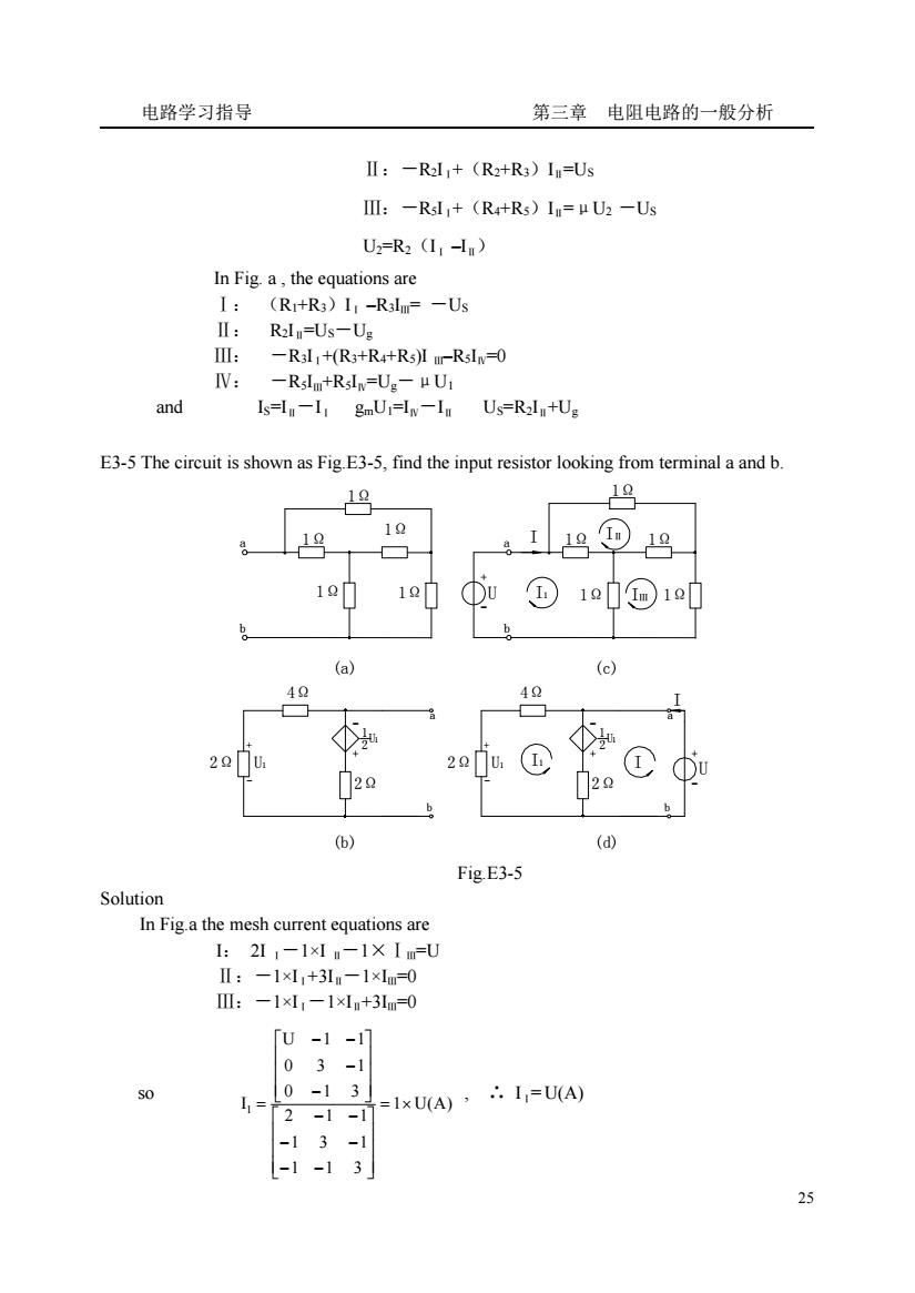
电路学习指导 第三章电阻电路的一般分析 Ⅱ:-Rl+(R+R3)In=Us III:-RsI+(R4+Rs)In=pU2-Us U2=R2(11-) In Fig a,the equations are I:(R+R3)I-R3Im=-Us R2I=Us-Ug -R3I:+(R3+R4+Rs)Iur-RsIn-0 V:-Rl+Rslw=U:-μU1 and Is=I-1 gmUi=I-In Us=R2In+U: E3-5 The circuit is shown as Fig.E3-5,find the input resistor looking from terminal a and b 19 19 9 1Q门 1 Du①1⊙1中 40 ①为 2 2u① 不U 20 (d) Fig.E3-5 Solution In Figa the mesh current equations are 1:211-1×"-1×I=U Ⅱ:-1×l1+311-1×lm=0 :-1×,-1×+3m-0 u-1-1 03-1 =1xUA·I=UA) -13-1 -1-13
电路学习指导 第三章 电阻电路的一般分析 25 Ⅱ:-R2IⅠ+(R2+R3)IⅡ=US Ⅲ:-R5IⅠ+(R4+R5)IⅡ=μU2 -US U2=R2(IⅠ –IⅡ) In Fig. a , the equations are Ⅰ: (R1+R3)IⅠ –R3IⅢ= -US Ⅱ: R2IⅡ=US-Ug Ⅲ: -R3IⅠ+(R3+R4+R5)I Ⅲ–R5IⅣ=0 Ⅳ: -R5IⅢ+R5IⅣ=Ug-μU1 and IS=IⅡ-IⅠ gmU1=IⅣ-IⅡ US=R2IⅡ+Ug E3-5 The circuit is shown as Fig.E3-5, find the input resistor looking from terminal a and b. 1Ω b a b a U + - I1 IⅡ IⅢ b a + - 2Ω U1 + - 1 2 U1 2Ω 2Ω 2Ω U1 - + + - 4Ω b a U 1 2 1 I1 I I -U + I 1Ω 1Ω 1Ω 1Ω 1Ω 1Ω 1Ω 1Ω 1Ω 4Ω (a) (c) (b) (d) Fig.E3-5 Solution In Fig.a the mesh current equations are I: 2I Ⅰ-1×I Ⅱ-1×ⅠⅢ=U Ⅱ:-1×IⅠ+3IⅡ-1×IⅢ=0 Ⅲ:-1×IⅠ-1×IⅡ+3IⅢ=0 so 1 U(A) 1 1 3 1 3 1 2 1 1 0 1 3 0 3 1 U 1 1 I 1 = × ⎥ ⎥ ⎥ ⎦ ⎤ ⎢ ⎢ ⎢ ⎣ ⎡ − − − − − − ⎥ ⎥ ⎥ ⎦ ⎤ ⎢ ⎢ ⎢ ⎣ ⎡ − − − − = , ∴ IⅠ= U(A)
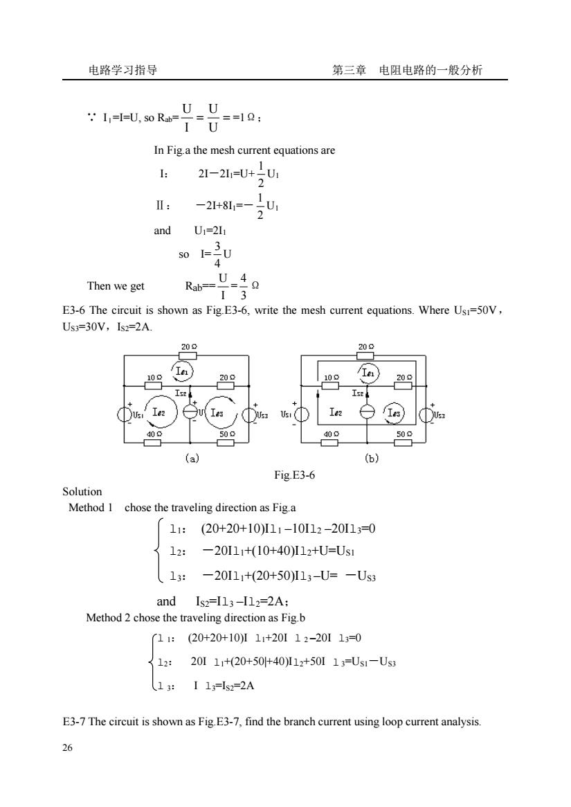
电路学习指导 第三章电阻电路的一般分析 I=I-U,s0R-U U 018: In Figa the mesh current equations are 21-2=U+U I: -21481,=-2U and U1=2I1 Then we get 4o Rab-13 E3-6 The circuit is shown as Fig.E3-6,write the mesh current equations.Where Usi=50V, Us3=30V,Is2=2A 20 白sx 109 509 (a) Fig.E3-6 Solution Method 1 chose the traveling direction as Fig.a 11:(20+20+10)I11-10I12-20I13=0 12: -20I11+(10+40)I12+U=Us1 13: -20111+(20+50)I13-U=-Us3 and 【s2=13-I12=2A: Method 2 chose the traveling direction as Fig.b 11:(20+20+10)11+20112-201130 12:20111+20+5040112+50113=Us1-Us 13 I12-2A E3-7 The circuit is shown as Fig.E3-7,find the branch current using loop current analysis. 26
电路学习指导 第三章 电阻电路的一般分析 26 ∵ IⅠ=I=U, so Rab= = = U U I U =1Ω; In Fig.a the mesh current equations are I: 2I-2I1=U+ 2 1 U1 Ⅱ: -2I+8I1=- 2 1 U1 and U1=2I1 so I= 4 3 U Then we get Rab== I U = 3 4 Ω E3-6 The circuit is shown as Fig.E3-6, write the mesh current equations. Where US1=50V, US3=30V,IS2=2A. Fig.E3-6 Solution Method 1 chose the traveling direction as Fig.a l1: (20+20+10)Il1 –10Il2 –20Il3=0 l2: -20Il1+(10+40)Il2+U=US1 l3: -20Il1+(20+50)Il3 –U= -US3 and IS2=Il3 –Il2=2A; Method 2 chose the traveling direction as Fig.b l 1: (20+20+10)I l1+20I l 2 –20I l3=0 l2: 20I l1+(20+50|+40)Il2+50I l 3=US1-US3 l 3: I l3=IS2=2A E3-7 The circuit is shown as Fig.E3-7, find the branch current using loop current analysis
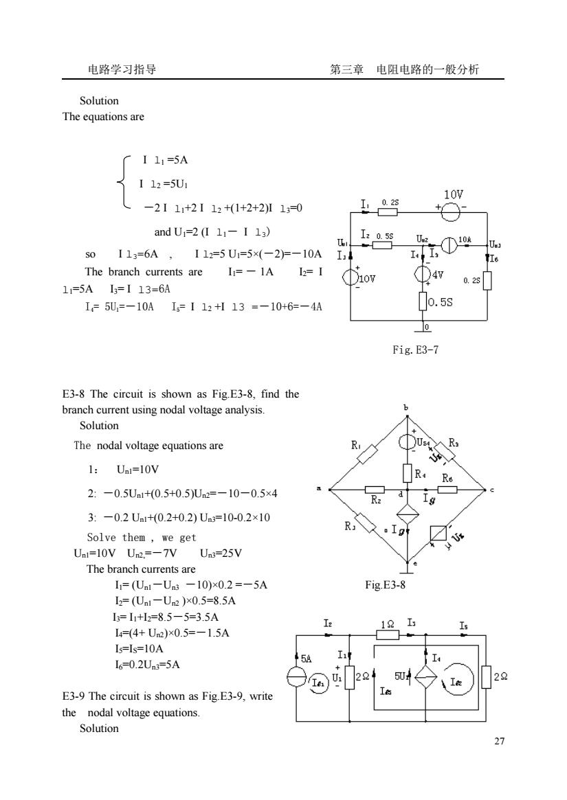
电路学习指导 第三章电阻电路的一般分析 Solution The equations are 厂I11=5A 112=5U1 10w -2111+2112+(1+2+2I10 andU=2(111-11) 名 3058 50113=6A, 112=5U1=5×(-2F-10A The branch currents are 1=-1A12=1 ①4 1=5A1=113=6A 28 1=5U,=-10A1=112+113=-10+6=-4A o.5s Fig.E3-7 E3-8 The circuit is shown as Fig.E3-8,find the branch current using nodal voltage analysis Solution The nodal voltage equations are 下Ua 1:Ua1=10V 门R 2:-0.5Un1+0.5+0.5)Un2=-10-0.5×4 R 3:-0.2Ua1+0.2+0.2)Un=10-0.2×10 Solve them,we get Unl=10V Un2.=-7V Un3=25V The branch currents are I=(U1-Un3-10)×02=-5A Fig.E3-8 l2=(Ua1-U)x0.5=8.5A l=11+l=8.5-5=3.5A 11 I6=0.2Un3=5A E3-9 The circuit is shown as Fig.E3-9,write the nodal voltage equations. Solution
电路学习指导 第三章 电阻电路的一般分析 27 Solution The equations are I l1 =5A I l2 =5U1 -2 I l1+2 I l2 +(1+2+2)I l3=0 and U1=2 (I l1- I l3) so I l3=6A , I l2=5 U1=5×(-2)=-10A The branch currents are I1= - 1A I2= I l1=5A I3= I l3=6A I4= 5U1=-10A I5= I l2 +I l3 =-10+6=-4A Fig.E3-7 E3-8 The circuit is shown as Fig.E3-8, find the branch current using nodal voltage analysis. Solution The nodal voltage equations are 1: Un1=10V 2: -0.5Un1+(0.5+0.5)Un2=-10-0.5×4 3: -0.2 Un1+(0.2+0.2) Un3=10-0.2×10 Solve them , we get Un1=10V Un2,=-7V Un3=25V The branch currents are I1= (Un1-Un3 -10)×0.2 =-5A Fig.E3-8 I2= (Un1-Un2 )×0.5=8.5A I3= I1+I2=8.5-5=3.5A I4=(4+ Un2)×0.5=-1.5A I5=IS=10A I6=0.2Un3=5A E3-9 The circuit is shown as Fig.E3-9, write the nodal voltage equations. Solution
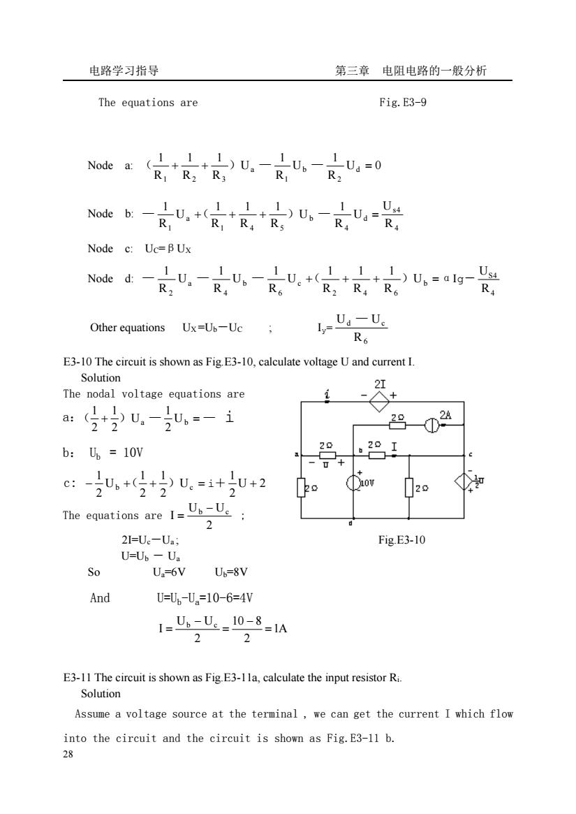
电路学习指导 第三章电阻电路的一般分析 The equations are Fig.E3-9 1 Node c:Uc=B Ux U,一R4 Noded:一R, U一R6 1 1.1)U.=alg-Ri Other equations Ux=Ub-Uc l-U-U. E3-10 The circuit is shown as Fig.E3-10,calculate voltage U and current I. Solution The nodal voltage equations are 20 b:=10v ce:知,+的u.=++2 20 The equations are 1-U-U 2 2l=Ue-Ua; Fig.E3-10 U=Uh-U. So U,=6V Up=8V And U=,-U.=10-6=4V 1-U-l08=1A 2 2 E3-11 The circuit is shown as Fig.E3-1la,calculate the input resistor Ri. Solution Assume a voltage source at the terminal,we can get the current I which flow into the circuit and the circuit is shown as Fig.E3-11 b. 28
电路学习指导 第三章 电阻电路的一般分析 28 The equations are Fig.E3-9 Node a: U 0 R 1 U R 1 U R 1 R 1 R 1 d 2 b 1 a 1 2 3 ( + + ) — — = Node b: 4 s4 d 4 b 1 4 5 a 1 R U U R 1 U R 1 R 1 R 1 U R 1 — +( + + ) — = Node c: UC=βUX Node d: + + + b = 2 4 6 c 6 b 4 a 2 U R 1 R 1 R 1 U R 1 U R 1 U R 1 — — — ( ) αIg- 4 S4 R U Other equations UX =Ub-UC ; Iy= 6 d c R U — U E3-10 The circuit is shown as Fig.E3-10, calculate voltage U and current I. Solution The nodal voltage equations are a:( + ) a — Ub = — 2 1 U 2 1 2 1 i b: Ub = 10V c: − b + + Uc = 2 1 2 1 U 2 1 ( ) i+ U 2 2 1 + The equations are 2 U U I b − c = ; 2I=Uc-Ua ; Fig.E3-10 U=Ub - Ua So Ua=6V Ub=8V And U=Ub-Ua=10-6=4V 1A 2 10 8 2 U U I b c = − = − = E3-11 The circuit is shown as Fig.E3-11a, calculate the input resistor Ri. Solution Assume a voltage source at the terminal , we can get the current I which flow into the circuit and the circuit is shown as Fig.E3-11 b
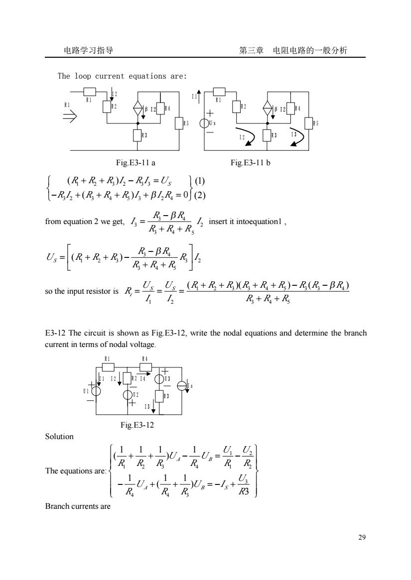
电路学习指导 第三章电阻电路的一般分析 The loop current equations are: us Fig.E3-11a Fig.E3-11b (R+R+R)山-R4=U1①) -R5+(R+R+R)M+B1,R=0(2) R-BR from equation 2 we get,= insert it intoequationl, R+R+Rs U,=(R+R+R) R-BR。R R+R+Rs so the input resistor is= U:-U:-(R+R+RXR+R+R)-R(R-BR) R+R+Rs E3-12 The circuit is shown as Fig.E3-12,write the nodal equations and determine the branch current in terms of nodal voltage. Fig.E3-12 Solution ,1 LUa-RR The equations are: ,+ ,1 0。=-+ Branch currents are 29
电路学习指导 第三章 电阻电路的一般分析 29 The loop current equations are: R 1 R 2 R 4 R 5 R 3 I 2 β I 2 R 1 R 1 R 2 R 4 R 5 R 3 β I 2 U s I 1 I 2 I 3 Fig.E3-11 a Fig.E3-11 b 1 2 3 2 3 3 3 2 3 4 5 3 2 4 ( ) (1) ( ) 0 (2) R R R I R I US R I R R R I I R β ⎧ ⎫ + + − = ⎨ ⎬ ⎩ ⎭ − + + + + = from equation 2 we get, 3 4 3 2 3 4 5 R R I I R R R − β = + + insert it intoequation1 , 3 4 1 2 3 3 2 3 4 5 ( ) S R R U R R R R I R R R ⎡ ⎤ − β = + + − ⎢ ⎥ ⎣ ⎦ + + so the input resistor is 1 2 3 3 4 5 3 3 4 1 2 3 4 5 ( )( ) ( ) S S i U U R R R R R R R R R R I I R R R + + + + − − β = = = + + E3-12 The circuit is shown as Fig.E3-12, write the nodal equations and determine the branch current in terms of nodal voltage. R 3 R 1 R 2 R 4 U 1 U 3 U 2 I s I 2 I 3 I 1 I 4 Fig.E3-12 Solution The equations are: 1 2 1 2 3 4 1 2 3 4 4 3 1 1 1 1 ( ) 1 1 1 ( ) 3 A B A B S U U U U R R R R R R U U U I R R R R ⎧ ⎫ + + − = − ⎪ ⎪ ⎪ ⎪ ⎨ ⎬ ⎪ ⎪ − + + = − + ⎪ ⎪ ⎩ ⎭ Branch currents are
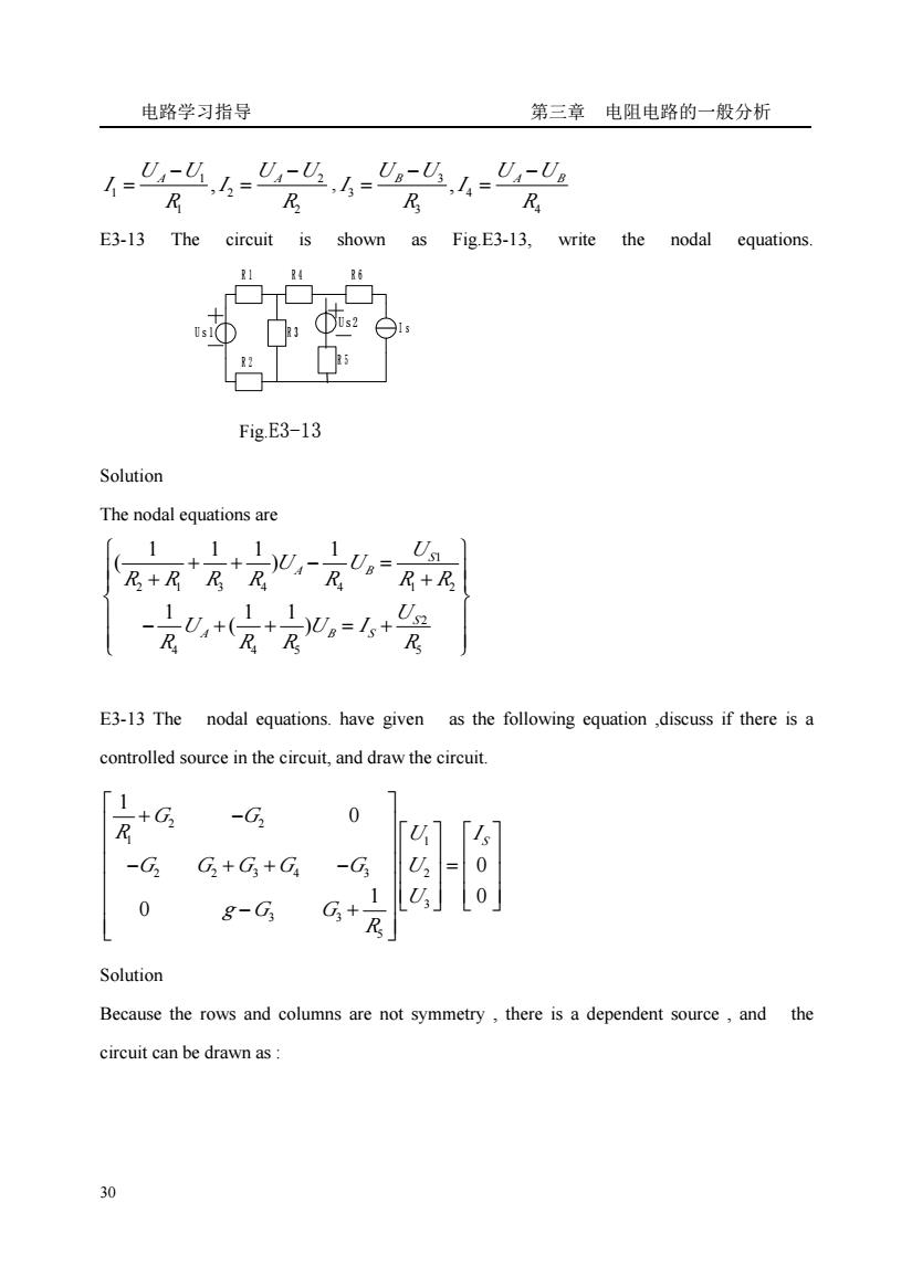
电路学习指导 第三章电阻电路的一般分析 R R E3-13 The circuit is shown as FigE3-13,write the nodal equations. 14 16 Th Fig.E3-13 Solution The nodal equations are 1 R R+R 20,=1+ R R E3-13 The nodal equations.have given as the following equation,discuss if there is a controlled source in the circuit,and draw the circuit. 「1 +G -G 0 U -G G+G3+G -G3 ,= 0 0 0 8-G Solution Because the rows and columns are not symmetry,there is a dependent source,and the circuit can be drawn as:
电路学习指导 第三章 电阻电路的一般分析 30 1 2 1 2 1 2 , U U U U A A I I R R − − = = , 3 3 4 3 4 , U U B U U A B I I R R − − = = E3-13 The circuit is shown as Fig.E3-13, write the nodal equations. R 1 R 4 R 6 R 3 R 2 R 5 I s U s 2 U s 1 Fig.E3-13 Solution The nodal equations are 1 2 1 3 4 4 1 2 2 4 4 5 5 1 1 1 1 ( ) 1 1 1 ( ) S A B S A B S U U U R R R R R R R U U U I R R R R ⎧ ⎫ + + − = ⎪ ⎪ ⎪ ⎪ + + ⎨ ⎬ ⎪ ⎪ − + + = + ⎪ ⎪ ⎩ ⎭ E3-13 The nodal equations. have given as the following equation ,discuss if there is a controlled source in the circuit, and draw the circuit. 2 2 1 1 2 2 3 4 3 2 3 3 3 5 1 0 0 1 0 0 S G G R U I G G G G G U U g G G R ⎡ ⎤ + − ⎢ ⎥ ⎡ ⎤ ⎡ ⎤ ⎢ ⎥ ⎢ ⎥ ⎢ ⎥ ⎢ ⎥ − + + − = ⎢ ⎥ ⎢ ⎥ ⎢ ⎥ ⎢ ⎥ ⎢ ⎥ ⎢ ⎥⎣ ⎦ ⎣ ⎦ − + ⎢ ⎥ ⎣ ⎦ Solution Because the rows and columns are not symmetry , there is a dependent source , and the circuit can be drawn as :