电路学习指导 第三章电阻电路的一般分析 CAPTER 7 SINUSOIDAL STEADY-STATE ANALYSIS 7-1 Introduction In chapter 9, we have learned how to apply Ohm's and Kirchhoff's laws to AC circuit. In this chapter, we want to see how nodal analysis, mesh analysis, Thevenin's theorem, Norton's theorem, superposition, and source transformations are applied in analyzing AC In this chapter we will discuss the analysis method, resonance and ac power analysis 7-2 Steps to analyze AC circuits 1 transform the circuit to phasor or frequency domain 2 solve the problem using circuit techniques (nodal analysis, mesh analysis, superposition,etc.) 3 transform the result phasor into time domain(required) X(w) col. 7-3Series ResonanceThe series R X(w) and C along with resistance jool. R is shown as Fig.7-1 U / The impedance is 0 Z=R+(L-) As wincrease, Z decrease, as w continue to increase, a point is reached where the reactance term is zero shown as Fig.7-2. When Do=VIC the circuit is resonant, we call it a series resonance or current resonance. Because in this condition,the current is maximum. The characteristic impedance and quality-factor are defined as 0am nono -or U8 R1 -mas.i- UR/U Q1<R2<R3 0 =-18 1 --100.P=Rr. 0.707 Q1 The phasor diagram is shown as Fig.7-3. Because Q2 Q3 0 1:y= 21
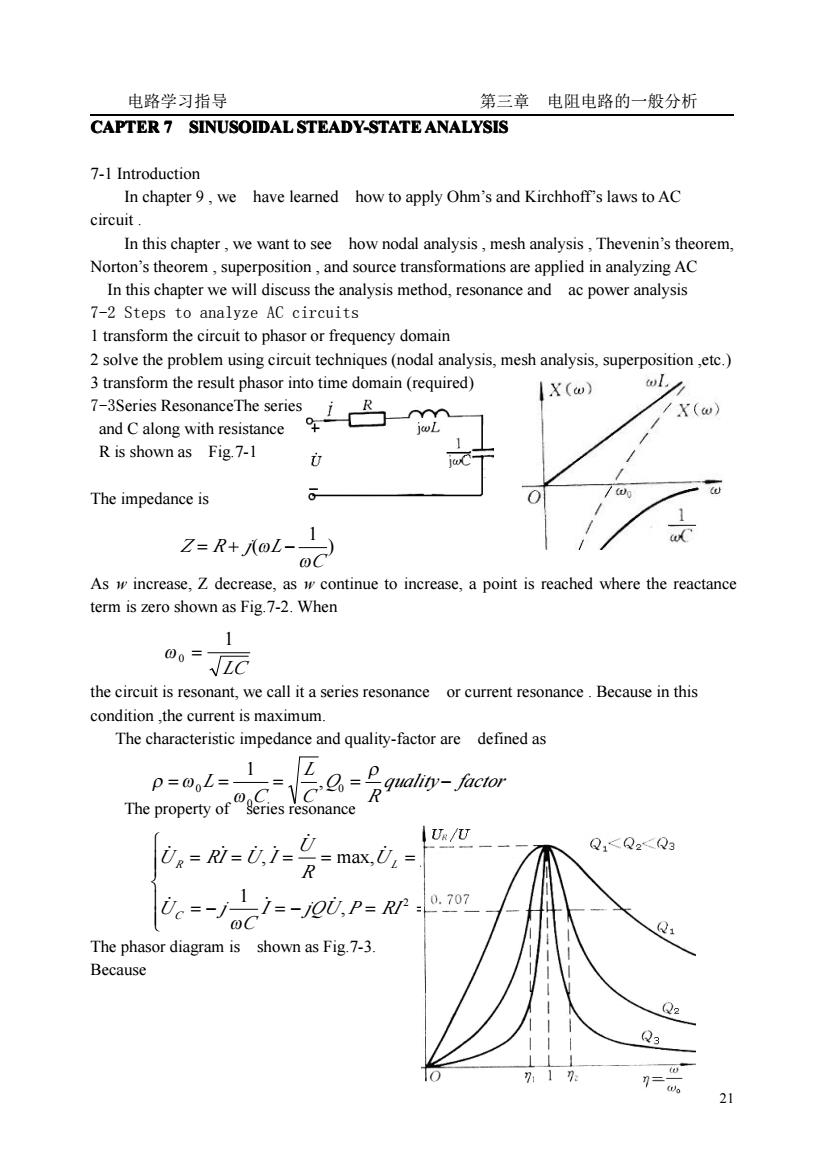
电路学习指导 第三章 电阻电路的一般分析 21 CAPTER 7 SINUSOIDAL SINUSOIDAL SINUSOIDAL SINUSOIDAL STEADY-STATE STEADY-STATE STEADY-STATE STEADY-STATE ANALYSIS ANALYSIS ANALYSIS ANALYSIS 7-1 Introduction In chapter 9 , we have learned how to apply Ohm’s and Kirchhoff’s laws to AC circuit . In this chapter , we want to see how nodal analysis , mesh analysis , Thevenin’s theorem, Norton’s theorem , superposition , and source transformations are applied in analyzing AC In this chapter we will discuss the analysis method, resonance and ac power analysis 7-2 Steps to analyze AC circuits 1 transform the circuit to phasor or frequency domain 2 solve the problem using circuit techniques (nodal analysis, mesh analysis, superposition ,etc.) 3 transform the result phasor into time domain (required) 7-3Series ResonanceThe series arrangement of L and C along with resistance R is shown as Fig.7-1 Fig.7-1 The impedance is Fig.7-2 As w increase, Z decrease, as w continue to increase, a point is reached where the reactance term is zero shown as Fig.7-2. When the circuit is resonant, we call it a series resonance or current resonance . Because in this condition ,the current is maximum. The characteristic impedance and quality-factor are defined as The property of series resonance The phasor diagram is shown as Fig.7-3. Because ) 1 ( C Z R j L ω = + ω − LC 1 ω 0 = quality factor R Q C L C = L = = = − ρ ω ρ ω 0 0 0 , 1 ⎪ ⎪ ⎩ ⎪⎪ ⎨ ⎧ = − = − = = = = = = = = , max 1 , max, 2 0 I jQU P RI C U j U j LI jQU R U U RI U I C R L ̇ ̇ ̇ ̇ ̇ ̇ ̇ ̇ ̇ ̇ ̇ ω ω
电路学习指导 第三章电阻电路的一般分析 2o)= OL 1 U,=RI-RZo II →Ue/U=1/V1+☑(-1/n)2 the resonant curve is shown as Fig.7-4 Fig.7-4 Fig.7-3 The higher the value ofQ,the more selective the circuit is but the smaller the bandwith BW=Q/f0 when Q>>1. 7-4 Parallel Resonance The parallel RLC circuit is the dual of the series RLC circuit shown as Fig.7-5.Admittance is Resonance occurs when the imaginary part of Y is zero.The frequency quality factor and 0。= 元awr 0=0C 1 LG 1=-j0I,=-1 7-5 The instantaneous power p(t)absorbed by an element is the product of the instantan-eous voltage u(t)across the element and the current i(t)through it.Suppose un)=U2 cos(@r+) The instantanebs pouecgs(+) This show)batheins8su36gasM件pp平9,)The first part is constant.Its value depends on the phase difference between the voltage and current.The second part is a sinusoidal function whose fre-quency is2 which is twice the angular frequency of the voltage or current shown as Fig.7 12
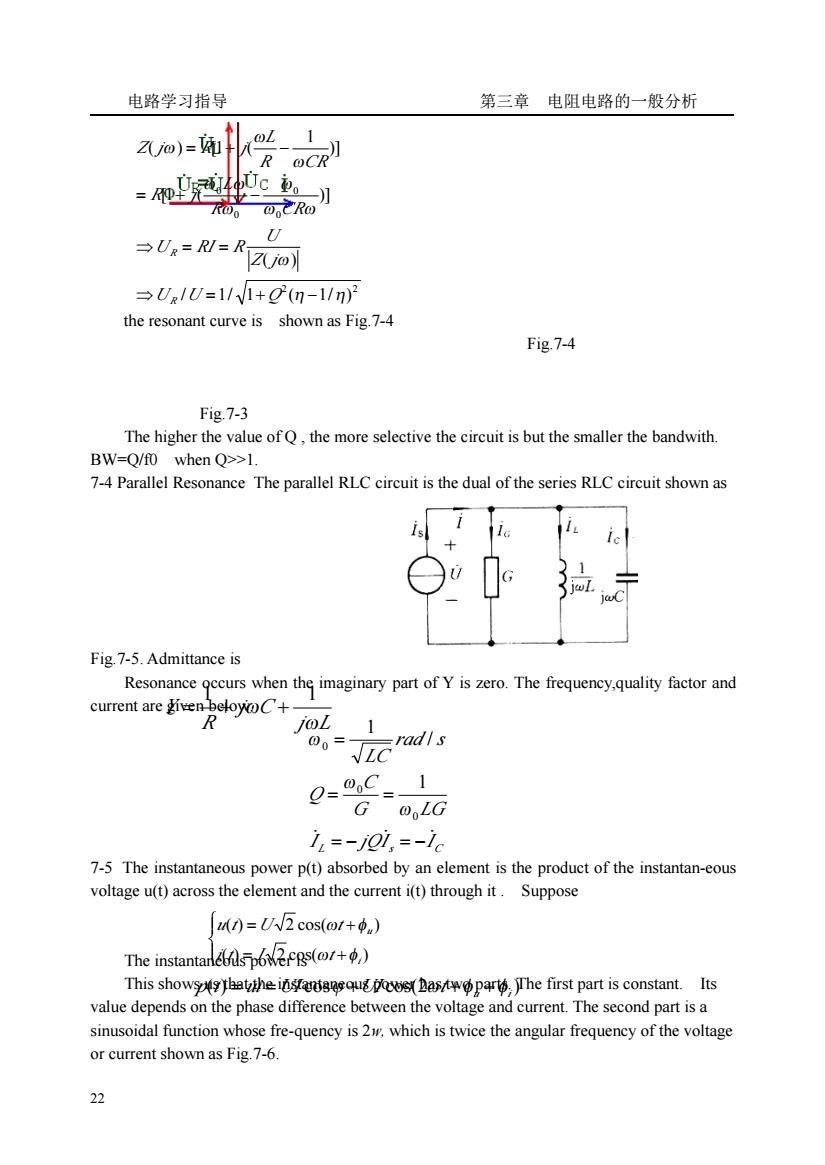
电路学习指导 第三章 电阻电路的一般分析 22 the resonant curve is shown as Fig.7-4 Fig.7-4 Fig.7-3 The higher the value of Q , the more selective the circuit is but the smaller the bandwith. BW=Q/f0 when Q>>1. 7-4 Parallel Resonance The parallel RLC circuit is the dual of the series RLC circuit shown as Fig.7-5. Admittance is Resonance occurs when the imaginary part of Y is zero. The frequency,quality factor and current are given below: 7-5 The instantaneous power p(t) absorbed by an element is the product of the instantan-eous voltage u(t) across the element and the current i(t) through it . Suppose The instantaneous power is This shows us that the instantaneous power has two parts. The first part is constant. Its value depends on the phase difference between the voltage and current. The second part is a sinusoidal function whose fre-quency is 2w, which is twice the angular frequency of the voltage or current shown as Fig.7-6. 2 2 0 0 0 0 / 1/ 1 ( 1/ ) ( ) [1 ( )] )] 1 ( ) [1 ( η η ω ω ω ω ω ω ω ω ω ω ⇒ = + − ⇒ = = = + − = + − U U Q Z j U U RI R R CR L R j R CR L Z j R j R R j L j C R Y ω ω 1 1 = + + L s C I jQI I G LG C Q rad s LC ̇ = − ̇ = − ̇ = = = 0 0 0 1 / 1 ω ω ω ⎪ ⎩ ⎪ ⎨ ⎧ = + = + ( ) 2 cos( ) ( ) 2 cos( ) iu i t I t u t U t ω φ ω φ ( ) cos cos(2 ) u i p t = ui =UI ϕ +UI ωt +φ +φ
电路学习指导 第三章电阻电路的一般分析 Average powerThus ndU7c0s-Re(7) P=RP P=0=P 9=0.-0 Power Apparent Power Power Factor and Complex Powe Consider the circuit(shown as Fig.7-7)and suppose the impedance are Zo Ry +ir Z=R+iX Ns S=U,m吃P P nd 3=m=P+0 r=百6aR,Z=,hsPm=U公 So the average power isApparent power,power factor,complex power,reactive (qua-drature)power are respectivelyTheir relationship are shown as Fig.7-8 Fig.7-8 7-7 Power Factor CorrectionMost domestic loads(washing machine,air conditioners, refrigerators)and industrial loads(motors)are inductive and operate at a low lagging power factor(i lag u).Although the inductive nature of the load cannot be changed,we can increase its pf.The process of increasing the pf without altering the voltage or cur-rent to the original load is known as pf correction.A inductive load's pf is corrected by deliberately installing a capacitor in parallel with the load as in the circuit shown as Fig.79 1i2) 23
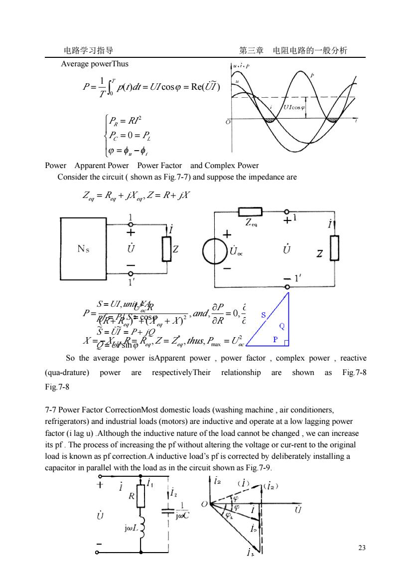
电路学习指导 第三章 电阻电路的一般分析 23 Average powerThus Fig.7-67-6 Maximum Power Apparent Power Power Factor and Complex Power Consider the circuit ( shown as Fig.7-7) and suppose the impedance are Fig.7-7 So the average power isApparent power , power factor , complex power , reactive (qua-drature) power are respectivelyTheir relationship are shown as Fig.7-8 Fig.7-8 7-7 Power Factor CorrectionMost domestic loads (washing machine , air conditioners, refrigerators) and industrial loads (motors) are inductive and operate at a low lagging power factor (i lag u) .Although the inductive nature of the load cannot be changed , we can increase its pf . The process of increasing the pf without altering the voltage or cur-rent to the original load is known as pf correction.A inductive load’s pf is corrected by deliberately installing a capacitor in parallel with the load as in the circuit shown as Fig.7-9. ) ~ ( ) cos Re( 1 0 p t dt UI UI T P T = = = ̇ ∫ ϕ ⎪ ⎩ ⎪ ⎨ ⎧ = − = = = u i C L R P P P RI ϕ φ φ 0 2 Zeq = Req + jX eq , Z = R + jX , , 0, 0 ( ) ( ) 2 2 2 = ∂ ∂ = ∂ ∂ + + + = X P R P and R R X X U R P eq eq oc eq eq eq P Uoc Req X X , R R ,Z Z ,thus, / 4 2 max * = − = = = ϕ ϕ sin ~ ~ / cos , , Q UI S UI P jQ pf P S S UI unit VA = = = + = = = ̇
电路学习指导 第三章电阻电路的一般分析 Fig.7-9 =/sino-/sino,/coso /coso from,P=Ul cos =Ulcosp C=IclUo PloU-(igo-igo) 7-8 Examples E7-1 The circuit is shown as Fig.E7-1,write the nodal voltage and mesh current equations. 凸0®5 + iΦ©1e@ ③ Fig.E7-1 Solution: Assume the third node as the reference node (or grouded).The nodal equationsare: 咖@:方+云 ☑2 Note the resistor which connected in series with the current sourceshould be omitted.It can not be shown in the self admittance and mutual admittance. The mesh equations are: Mesh①:(☑+Z)ial-Zim=ii Mesh②:-Z3lnml+(Z+☑+Z)1m2-Zams=-U3 Mesh③:/m=-lss E7-2 The circuit is shown as Fig.E7-2,write the nodal voltage and mesh current equations. Solution: Choose D as the reference node,then the nodal equations are 24
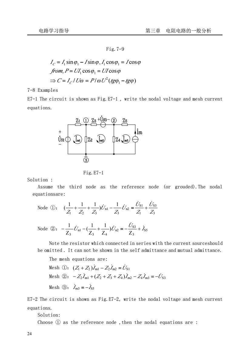
电路学习指导 第三章 电阻电路的一般分析 24 Fig.7-9 7-8 Examples E7-1 The circuit is shown as Fig.E7-1 , write the nodal voltage and mesh current equations. Fig.E7-1 Solution : Assume the third node as the reference node (or grouded).The nodal equationsare: Node ①: 1 ) 1 1 1 ( 3 S3 1 S1 n2 3 n1 1 2 3 Z U Z U U Z U Z Z Z ̇ ̇ + + ̇ − ̇ = + Node ②: S5 3 S3 n2 3 4 n1 3 Z ) Z 1 Z 1 ( Z 1 I U U U ̇ ̇ − ̇ − + ̇ = − + Note the resistor which connected in series with the current sourceshould be omitted . It can not be shown in the self admittance and mutual admittance. The mesh equations are: Mesh ①: (Z1 Z2 )I m1 Z2 I m2 US1 + ̇ − ̇ = ̇ Mesh ②: Z2 I m1 (Z2 Z3 Z4 )I m2 Z4 I m3 US3 − ̇ + + + ̇ − ̇ = − ̇ Mesh ③: I m3 IS5 ̇ ̇ = − E7-2 The circuit is shown as Fig.E7-2, write the nodal voltage and mesh current equations. Solution: Choose ① as the reference node ,then the nodal equations are : / / ( ) , cos cos sin sin , cos cos 1 2 1 1 1 1 1 1 ω ω ϕ ϕ ϕ ϕ ϕ ϕ ϕ ϕ C I U P U tg tg from P UI UI I I I I I C C ⇒ = = − = = = − =
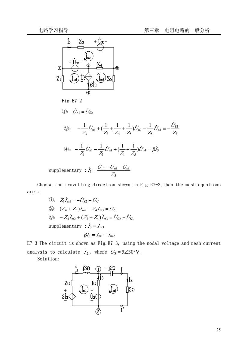
电路学习指导 第三章电阻电路的一般分析 +0e ②Z4 +③ ④ Fig.E7-2 ①:Unl=i supplementarya-U Z Choose the travelling direction shown in Fig.E7-2,then the mesh equations are ①:Zim=-02-0c ②:(Z+Z)lm-Zm=Uc ③:-Zim+(Z+Za)lm=i2-i3 supplementary /3=/m3 Bls=/ml-72 E7-3 The circuit is shown as Fig.E7-3,using the nodal voltage and mesh curren analysis to calculate/,where=5∠30V Solution: 3 2n0 13m ② 25
电路学习指导 第三章 电阻电路的一般分析 25 Fig.E7-2 ①:Un1 US2 ̇ ̇ = ③: 3 S3 n4 5 n2 3 4 5 n1 3 1 ) 1 1 1 ( 1 Z U U Z U Z Z Z U Z ̇ − ̇ + + + ̇ − ̇ = − ④: n4 3 1 5 n3 5 n1 1 ) 1 1 ( 1 1 U I Z Z U Z U Z − ̇ − ̇ + + ̇ = β̇ supplementary : 3 n1 n3 s3 3 Z U U U I ̇ ̇ ̇ ̇ − − = Choose the travelling direction shown in Fig.E7-2,then the mesh equations are : ①: Z1I m1 US2 UC ̇ = − ̇ − ̇ ②: Z Z I Z I UC + ̇ − ̇ = ̇ ( 4 5 ) m2 4 m3 ③: Z4 I m2 (Z3 Z4 )I m3 US2 US3 − ̇ + + ̇ = ̇ − ̇ supplementary : I 3 I m3 ̇ = ̇ I 3 I m1 I m2 β̇ = ̇ − ̇ E7-3 The circuit is shown as Fig.E7-3, using the nodal voltage and mesh current analysis to calculate 2 I ̇ , where U̇S = 5∠30°V . Solution:
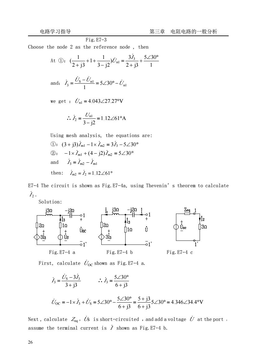
电路学习指导 第三章电阻电路的一般分析 Fig.E7-3 Choose the node 2 as the reference node,then 1 3/5∠30 At0:2+B*1+3-20=2+B+ ad方=么-么=5230m- we get Ul =4.043227.27V Using mesh analysis,the equations are: ①:(3+j3)7m1-1×1m2=33-5∠30° ②:-1x1nt+(4-j2)1nm=5∠30 and 3=/m2-/m then:im2=2=l.12∠61° E7-4 The circuit is shown as Fig.E7-4a,using Thevenin's theorem to calculate Solution: 01 Zeg 1 1 02n 20 Uoc 01n /3n 3 Φis ④3is 1 1 Fig.E7-4 a Fig.E7-4 b Fig.E7-4 c First,calculate Uoc shown as Fig.E7-4 a. 6=-3坊 3+3 6=5∠30 6+j3 ioc=-1x方+=5∠30°-5∠30°-5+i25∠30°=4346∠34.4v 6+j36+j3 Next,calculate Z,Us is short-circuited,and add a voltage U at the port assume the terminal current is shown as Fig.E7-4 b. 26
电路学习指导 第三章 电阻电路的一般分析 26 Fig.E7-3 Choose the node 2 as the reference node , then At ①: 1 5 30 2 j3 3 ) 3 j2 1 1 2 j3 1 ( 3 n1 ∠ ° + + = − + + + I U ̇ ̇ and: n1 S n1 3 5 30 1 U U U I ̇ ̇ ̇ ̇ = ∠ ° − − = we get :U̇ n1 = 4.043∠27.27°V ∴ 1.12 61 A 3 j2 n1 2 = ∠ ° − = U I ̇ Using mesh analysis, the equations are: ①: (3 + j3)I m1 −1× I m2 = 3I 3 − 5∠30° ̇ ̇ ̇ ②: −1× I m1 + (4 − j2)I m2 = 5∠30° ̇ ̇ and I 3 I m2 I m1 ̇ = ̇ − ̇ then: I m2 = I 2 =1.12∠61° ̇ ̇ E7-4 The circuit is shown as Fig.E7-4a, using Thevenin’s theorem to calculate 2 I ̇ . Solution: Fig.E7-4 a Fig.E7-4 b Fig.E7-4 c First, calculate UOC ̇ shown as Fig.E7-4 a. 3 j3 S 3 3 3 + − = U I I ̇ ̇ ̇ ∴ 6 j3 5 30 3 + ∠ ° I = ̇ 5 30 4.346 34.4 V 6 j3 5 j3 6 j3 5 30 OC 1 3 S 5 30 ∠ ° = ∠ ° + + = + ∠ ° U = − × I +U = ∠ ° − ̇ ̇ ̇ Next , calculate Zeq ,Uṡ is short-circuited ,and add a voltage U̇ at the port , assume the terminal current is I ̇ shown as Fig.E7-4 b

电路学习指导 第三章电阻电路的一般分析 0=-j2i-3 {(2+j3)1+313+1=0(2) 4=1+3 (3) 50方=-2+) 6+3 insert it to equation (1).we get:2+ 6+j3 6+j3 s乙-号-3-1754-48阳 according Fig.E7-4 c, Uoc h=3+Z -=1.12∠61A E7-5 The circuit is shown as Fig.E7-5,using three meters to measure the parameters Rand L of the inductor coil,where V=50V,A=IA,W=30W /=50HZ.Determine:)the values of R L:(2)the complex power absorbed by the coil. Solution: The reading of the voltmeter and ammeter boths are the effective values,The reading of the powermeter is the average power absorbed by the coil (1)According to P=U/cos Fig.E7-5 p_30=0.6 We get cos50 =cos市0.6=53.13° Z=|A∠D=R+joL 月-n .R+joL=50∠53.13°=(30+j40)2 40 R=302,oL=402,∠=314=127mH 27
电路学习指导 第三章 电阻电路的一般分析 27 ⎪ ⎩ ⎪ ⎨ ⎧ = + + + + = = − − (3) (2 j3) 3 0 (2) j2 (1) 1 3 1 3 3 3 I I I I I I U I I ̇ ̇ ̇ ̇ ̇ ̇ ̇ ̇ ̇ so I I ̇ ̇ 6 j3 (2 j3) 3 + − + = insert it to equation (1), we get :U I I I ̇ ̇ ̇ ̇ 6 j3 8 j9 6 j3 2 j3 j2 + − = + + = − + thus = ∠ − °Ω + − = = 1.795 74.93 6 j3 8 j9 eq I U Z ̇ ̇ according Fig.E7-4 c , 1.12 61 A 3 eq OC 2 = ∠ ° + = Z U I ̇ ̇ E7-5 The circuit is shown as Fig.E7-5, using three meters to measure the parameters R and L of the inductor coil ,where V = 50V , A =1A , W = 30W , f = 50HZ .Determine:(1)the values of R、 L;(2)the complex power S absorbed by the coil. Solution: The reading of the voltmeter and ammeter both are the effective values , The reading of the powermeter is the average power absorbed by the coil (1) According to P =UI cosΦ Fig.E7-5 We get 0.6 50 30 cos = = = UI P Φ = cos 0.6 = 53.13° -1 Φ Φ Z = Z ∠Φ= R + jωL = = 50Ω I U Z ∴ R + jωL = 50∠53.13° = (30 + j40)Ω R = 30Ω , ωL = 40Ω , 127mH 314 40 L = =

电路学习指导 第三章电阻电路的一般分析 (2)calculate the S assume0=50∠0V,thus1-1∠-53.13°A 5=i=50∠0°×1∠+53.13°=(30+j40)VA P=30W =40VAR E7-6 The one porty without independent sources is shown as Fig.E7-6, u=1002cos(or+120V,i=52cosa1+60)A Determine'人,S,P, O and cos. 2 Solution U=100∠120V,7=5∠60°A 9 Z-9-100220°=2026090=00+j17320 Fig.E7-6 5∠60° ↓=0.05-60S 5=0=100∠120°×5∠-60°=500∠60VA=(250+j433)VA P=250W,Q=433VAR,S=500VA E7-7The circuit is shown as Fig.E7-7,U=38020V,=50HZ.the inductive load absorbs the power is =20kW,cos=0.6,if we want to improve the power factor to cos=0.9,determine the value of the corrective capacitor. R 0 1 Fig.E7-7a Fig.E7-7b Solution: cos4=0.6,h=cos10.6=53.13°,C= 示g4-g吻
电路学习指导 第三章 电阻电路的一般分析 28 (2)calculate the S assume U̇ = 50∠0°V ,thus I ̇ = 1∠ − 53.13°A = = 50∠0°×1∠ + 53.13° = (30 + j40)VA ∗ S UI ̇̇ P = 30W Q = 40VAR E7-6 The one porty without independent sources is shown as Fig.E7-6, u =100 2 cos(ωt +120°)V , i = 5 2 cos(ωt + 60°)A Determine Zeq ,Yeq , S , S , P , Q and cosΦ. Solution: U̇ =100∠120°V , I ̇ = 5∠60°A = ∠ °Ω = + Ω ∠ ° ∠ ° = = 20 60 (10 j17.32) 5 60 100 120 eq I U Z ̇ ̇ Fig.E7-6 0.05 60 S 1 eq eq = = = ∠ − ° U Z I Y ̇ ̇ = =100∠120°×5∠ − 60° = 500∠60°VA = (250 + j433)VA ∗ S UI ̇̇ P = 250W , Q = 433VAR , S = 500VA cos = = cos 60° = 0.5 S P Φ E7-7The circuit is shown as Fig.E7-7 , U̇ = 380∠0°V , f = 50HZ .the inductive load absorbs the power is P1 = 20kW , cosΦ1 = 0.6,if we want to improve the power factor to cosΦ= 0.9 ,determine the value of the corrective capacitor.。 Fig.E7-7a Fig.E7-7b Solution: cosΦ1 = 0.6 , = = ° − cos 0.6 53.13 1 Φ1 , (tg 1 tg ) 2 Φ Φ U P C = − ω
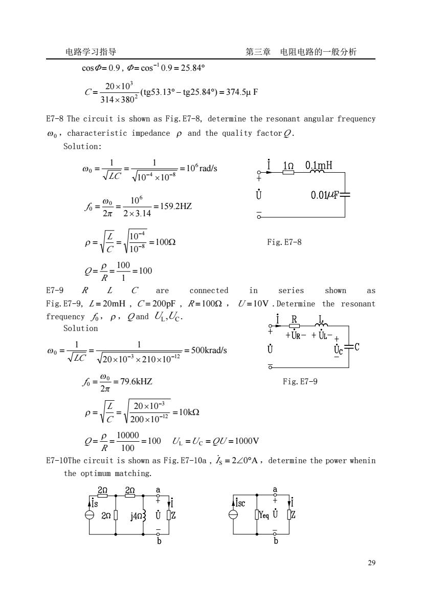
电路学习指导 第三章电阻电路的一般分析 c0sD=0.9,p=cos10.9=25.84° C 20×103 314×380g53.13°-g25.849)=3745uF E7-8 The circuit is shown as Fig.E7-8,determine the resonant angular frequency @o,characteristic impedance p and the quality factor. Solution: 00= VZ元10-x10 =10rad/s 1 oumi 106 0 0.01F- 人-尝2=1592 Z104 -yio100 Fig.E7-8 0-=分-10-100 1 E7-9 R L C are connected in series shown as Fig.E7-9,L=20mH,C=200pF,R=1002,U=10V.Determine the resonant frequency p,Qand .Uc. 1山 Solution +UR-+UL-+ 00= 元20x10r×210x10=50kads Uc- 6 6 2=796kH2 Fig.E7-9 Z20x10-3 p-V2-200x10=10k g=会l0-lm么-c=0u-inv E7-10The circuit is shown as Fig.E7-10a,/s=220A,determine the power whenin the optimum matching. 29 i 白2n0 68 29
电路学习指导 第三章 电阻电路的一般分析 29 cosΦ= 0.9 , = = ° − cos 0.9 25.84 1 Φ (tg53.13 tg25.84 ) 374.5μ F 314 380 20 10 2 3 ° − ° = × × C = E7-8 The circuit is shown as Fig.E7-8, determine the resonant angular frequency ω0 ,characteristic impedance ρ and the quality factor Q . Solution: 10 rad/s 10 10 1 1 6 4 8 0 = × = = LC − − ω 159.2HZ 2 3.14 10 2 6 0 0 = × = = π ω f = = − = Ω − 100 10 10 8 4 C L ρ Fig.E7-8 100 1 100 = = = R Q ρ E7-9 R L C are connected in series shown as Fig.E7-9, L = 20mH , C = 200pF , R =100Ω , U =10V .Determine the resonant frequency f 0 , ρ ,Q and L C U ,U . Solution 500krad/s 20 10 210 10 1 1 3 12 0 = × × × = = LC − − ω 79.6kHZ 2 0 0 = = π ω f Fig.E7-9 = Ω × × = = − − 10k 200 10 20 10 12 3 C L ρ 100 100 10000 = = = R Q ρ UL =UC = QU =1000V E7-10The circuit is shown as Fig.E7-10a , I ̇S = 2∠0°A ,determine the power whenin the optimum matching
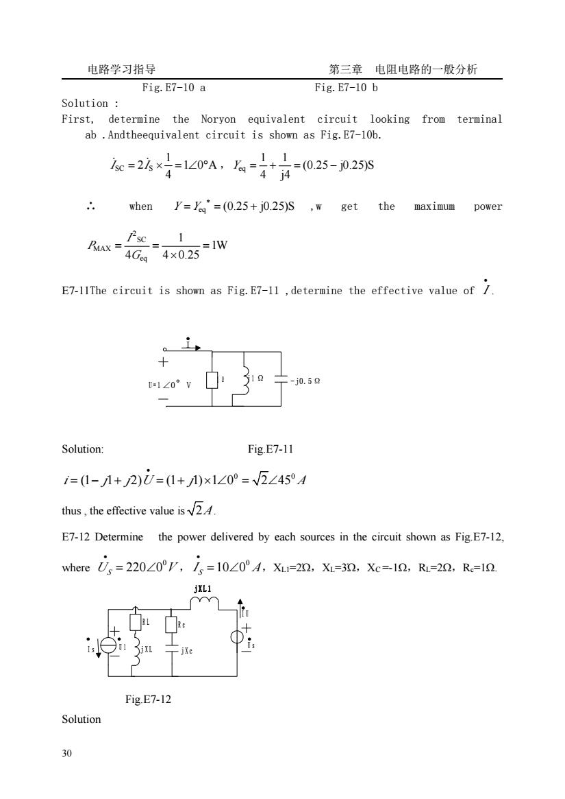
电路学习指导 第三章电阻电路的一般分析 Fig.E7-10 a Fig.E7-10 b Solution First,determine the Noryon equivalent circuit looking from terminal ab.Andtheequivalent circuit is shown as Fig.E7-10b. 4 when Y==(0.25+j0.25)S ,w get the maximum power 1 w-4C产4x025W E7-1IThe circuit is shown as Fig.E7-11,determine the effective value of 1 -j0.50 Solution Fig.E7-11 1=1-1+2)U=(1+)×1∠0°=2∠45°A thus,the effective value is E7-12 Determine the power delivered by each sources in the circuit shown as Fig.E7-12, where,=220z0°V,i,=10∠0°4,X-=2n,X=30,Xc=10,R=-20,R=1n Fig.E7-12 Solution 30
电路学习指导 第三章 电阻电路的一般分析 30 Fig.E7-10 a Fig.E7-10 b Solution : First, determine the Noryon equivalent circuit looking from terminal ab .Andtheequivalent circuit is shown as Fig.E7-10b. 1 0 A 4 1 ISC = 2IS × = ∠ ° ̇ ̇ , (0.25 j0.25)S j4 1 4 1 Yeq = + = − ∴ when = eq = (0.25 + j0.25)S ∗ Y Y ,w get the maximum power 1W 4 0.25 1 4 eq SC 2 MAX = × = = G I P E7-11The circuit is shown as Fig.E7-11 ,determine the effective value of I • . U = 1 ∠0°V 1 Ω j 1 Ω -j0.5Ω I Solution: Fig.E7-11 0 0 i j j U j A (1 1 2) (1 1) 1 0 2 45 • = − + = + × ∠ = ∠ thus , the effective value is 2A. E7-12 Determine the power delivered by each sources in the circuit shown as Fig.E7-12, where 0 220 0 U V S • = ∠ , 0 10 0 S I A • = ∠ ,XL1=2Ώ,XL=3Ώ,XC =-1Ω,RL=2Ω,Rc=1Ω. j X L 1 U 1 I U I s j X L j X c R c R L U s Fig.E7-12 Solution