第26卷第7期 半导体学报 Vol.26 No.7 2005年7月 CHINESE JOURNAL OF SEMICONDUCTORS July.2005 Patterned Dual pn Junctions Restraining Substrate Loss of an On-Chip Inductor* Jian Hongyan,Tang Jue,Tang Zhangwen,He Jie,and Min Hao (State Key Laboratory of ASIC &System,Fudan University,Shanghai 200433,China) Abstract:Dual pn junctions in lateral and vertical directions are formed by diffusing the p+on the patterned n-well in standard CMOS technology,which are inserted under the inductor in order to reduce the currents in the substrate induced by the electromagnetic field from the inductor.The thickness of high resistance is not equivalent to the width of the depletion region of the vertical pn junctions,but the depth of the bottom pn junction in the substrate are both proposed and validated.For the first time,through the grounded p+-diffusion layer shielding the substrate from the electric field of the inductor,the width of the depletion regions of the lateral and vertical pn junctions are changed by increasing the voltage applied to the n-wells.The quality factor is improved or reduced with the thickness of high re- sistance by 19%.This phenomenon validates the theory that the pn junction substrate isolation can reduce the loss caused by the currents in the substrate induced by the electromagnetic field from the inductor. Key words:on-chip inductor;patterned dual pn junctions;eddy current;substrate loss EEACC:2140;2530B;2550F CLC number:TM55 Document code:A Article ID:0253-4177(2005)07-1328-06 the resistance of the substratel3.4]can reduce the 1 Introduction eddy currents in the substrate and increase Q. These methods are not standard technology.The Monolithic inductors are important compo-inductor designers aim at realizing a substantially nents in highly integrated radio frequency circuits greater quality factor at circuit operation frequency for wireless communication systems such as a low-without altering the fabrication process,through noise amplifier,a voltage-controlled oscillator,and such methods as using a symmetric inductor that is an impedance matching network.However,on-chip excited differentially[5].Several papers[6-8]have re- inductors have a low quality factor (Q)due to met-ported the singe pn junction substrate isolation, al ohmic loss and conductive silicon substrate loss.however,dual pn junction substrate isolation struc- Many researchers have found several methods to tures without altering the fabrication process have improve the Q of on-chip inductor1]. not been reported and the reasons this structure The use of a patterned ground shield (PGS)[2] can reduce the substrate loss have not been reliably between the inductor metal trace and substrate in- validated by tape-out experiments.The eddy cur- creases Q by reducing the loss of electric energy rent would be formed in an n-well that is designed due to the current induced in a silicon substrate, as a whole layer6,which is larger than the sub- while at the same time not reducing the eddy cur-strate because the resistance of the n-well is less rent,which can significantly reduce Q.Increasing than that of the substrate. Project supported by the Shanghai Science 8.Technology Committee(No.037062019)and the Shanghai Applied Material Founds(No.0425) Jian Hongyan male,PhD candidate.His interested research directions include on-chip inductor and antenna optimization,RF circuits design such as LNA,mixer,VCO,and Antenna design for RFID.Email:hyjian@fudan.edu.cn Received 9 December 2004,revised manuscript received 24 January 2005 ©2005 Chinese Institute of Electronics
第B_卷 第M期 BWWV年M月 半 导 体 学 报 58JNE1EYRbPN!?RF1EDJ5RNUb5QRP1 H(#cB_ N(cM Y2#6!BWWV #+.(@;%’72""(.’;,G6’4;14&)34&$1%$;)%;r Q;%4)(#(365(00$’’;;"N(cWZMW_BWAS#&),’4;14&)34&$!""#$;,D&’;.$&#F(2),7"N(cWXBV# Y$&)8()36&) 0&#;!+4U%&),$,&’;c8$7$)’;.;7’;,.;7;&.%4,$.;%’$()7$)%#2,;()[%4$"$),2%’(.&),&)’;))&("’$0$:&’$()!PF%$.%2$’7,;7$3) 72%4&7?N!!0$/;.!H5R!&),!)’;))&,;7$3)*(.PFJUcE0&$#$46@$&)"*2,&)c;,2c%) P;%;$O;,SU;%;0G;.BWWX!.;O$7;,0&)27%.$"’.;%;$O;,BXY&)2&.6BWWV #BWWV54$);7;J)7’$’2’;(*E#;%’.()$%7 BC??>@H>L$A?@CJHJHR259AA 9MCH%HV0IJD’HL=T9@LA$()[%4$"$),2%’(.%"&’’;.);,,2&#")@2)%’$()7%;,,6%2..;)’%72G7’.&’;#(77 **"00$BAXW%BVZWI%BVVWF 050H@$QDVV $9NH?N9L>$! "@?JN:>’$$WBVZ[XAMM"BWWV#WM[AZBC[W_ E ’H?@9L<N?J9H D()(#$’4$%$),2%’(.7 &.;$0"(.’&)’ %(0"([ );)’7$)4$34#6$)’;3.&’;,.&,$(*.;]2;)%6%$.%2$’7 *(.T$.;#;77%(002)$%&’$()767’;0772%4&7&#(T[ )($7;&0"#$*$;.!&O(#’&3;[%()’.(##;,(7%$##&’(.!&), &)$0";,&)%;0&’%4$)3);’T(.^c8(T;O;.!()[%4$" $),2%’(.74&O;&#(T]2&#$’6*&%’(.",#,2;’(0;’[ &#(40$%#(77&),%(),2%’$O;7$#$%()72G7’.&’;#(77c D&)6.;7;&.%4;.74&O;*(2),7;O;.�’4(,7’( $0".(O;’4;,(*()[%4$"$),2%’(.&A’ c Q4;27;(*&"&’’;.);,3.(2),74$;#,"+=1#&B’ G;’T;;)’4;$),2%’(.0;’&#’.&%;&),72G7’.&’;$)[ %.;&7;7, G6.;,2%$)3’4;#(77(*;#;%’.$%;);.36 ,2;’(’4;%2..;)’$),2%;,$)&7$#$%()72G7’.&’;! T4$#;&’’4;7&0;’$0;)(’.;,2%$)3’4;;,,6%2.[ .;)’!T4$%4%&)7$3)$*$%&)’#6.;,2%;,cJ)%.;&7$)3 ’4;.;7$7’&)%;(*’4;72G7’.&’;&Z!X’%&).;,2%;’4; ;,,6%2..;)’7$)’4;72G7’.&’;&),$)%.;&7; ,c Q4;7; 0;’4(,7&.;)(’7’&),&.,’;%4)(#(36cQ4; $),2%’(.,;7$3);.7&$0&’.;&#$:$)3&72G7’&)’$&##6 3.;&’;.]2&#$’6*&%’(.&’%$.%2$’(";.&’$()*.;]2;)%6 T$’4(2’&#’;.$)3’4;*&G.$%&’$() ".(%;77!’4.(234 72%40;’4(,7&727$)3&7600;’.$%$),2%’(.’4&’$7 ;/%$’;,,$**;.;)’$&##6&V’ c1;O;.&#"&";.7&_$C’ 4&O;.;[ "(.’;,’4;7$)3;")@2)%’$()72G7’.&’;$7(#&’$()! 4(T;O;.!,2&#")@2)%’$()72G7’.&’;$7(#&’$()7’.2%[ ’2.;7T$’4(2’&#’;.$)3’4;*&G.$%&’$()".(%;774&O; )(’G;;).;"(.’;,&),’4;.;&7()7’4$77’.2%’2.; %&).;,2%;’4;72G7’.&’;#(774&O;)(’G;;).;#$&G#6 O&#$,&’;,G6’&";[(2’;/";.$0;)’7cQ4;;,,6%2.[ .;)’T(2#,G;*(.0;,$)&))[T;##’4&’$7,;7$3);, &7&T4(#;#&6;.&_’!T4$%4$7#&.3;.’4&)’4;72G[ 7’.&’;G;%&27;’4;.;7$7’&)%;(*’4;)[T;##$7#;77 ’4&)’4&’(*’4;72G7’.&’;c
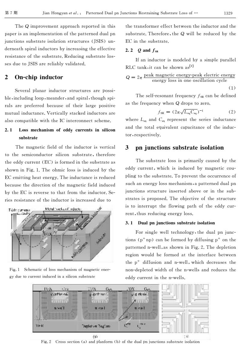
第7期 Jian Hongyan et al.Patterned Dual pn Junctions Restraining Substrate Loss of... 1329 The Q improvement approach reported in this the transformer effect between the inductor and the paper is an implementation of the patterned dual pn substrate.Therefore,the Q will be reduced by the junctions substrate isolation structures (JSIS)un- EC in the substrate. derneath spiral inductors by increasing the effective 2.2 0 and fsR resistance of the substrate.Reducing substrate los- If an inductor is modeled by a simple parallel ses due to JSIS are reliably validated. RLC tank,it can be shown ast2] 2 On-chip inductor Q-2xpeak magnetic energy-peak electric energy energy loss in one oscillation cycle (1) Several planar inductor structures are possi- ble,including loop,meander,and spiral,though spi- The self-resonant frequency fsR can be defined rals are preferred because of their large positive as the frequency when Q drops to zero. mutual inductance.Vertically stacked inductors are fsR=(2π√LC)- (2) also compatible with the IC interconnect scheme. where Leg and C represent the series inductance 2.I Loss mechanism of eddy currents in silicon and the total equivalent capacitance of the induc- tor,respectively. substrate The magnetic field of the inductor is vertical 3 pn junctions substrate isolation to the semiconductor silicon substrate,therefore the eddy current(EC)is formed in the substrate as The substrate loss is primarily caused by the shown in Fig.1.The ohmic loss is induced by the eddy current,which is induced by magnetic cou- EC emitting heat energy.The inductance is reduced pling to the substrate.To prevent the occurrence of because the direction of the magnetic field induced such an energy loss mechanism,a patterned dual pn by the EC is reverse to that from the inductor.Se- junctions structure inserted above or in the sub- ries resistance of the inductor is increased due to strates is proposed.The objective of the structure Miclal 'ckoul'much is to interrupt the flowing path of the eddy cur- Tidle menus 巴岁 rent,thus reducing energy loss. 3.I Dual pn junctions substrate isolation For single well technology,the dual pn junc- tions (pnp)can be formed by diffusing p on the patterned n-well,as shown in Fig.2.The depletion region would be formed at the interface between the p diffusion and n-well,which decreases the Fig.I Schematic of loss mechanism of magnetic ener- non-depleted width of the n-wells and reduces the gy due to current induced in a silicon substrate eddy current in the n-wells. 整义 on drf'ac- d r:si JJeplerom 3e:in iai 1 Fig.2 Cross section (a)and planform (b)of the dual pn junctions substrate isolation
第M期 Y$&)8()36&)*M#8T! +&’’;.);,U2&#")Y2)%’$()7P;7’.&$)$)312G7’.&’;?(77(*" Q4;,$0".(O;0;)’&"".(&%4.;"(.’;,$)’4$7 "&";.$7&)$0"#;0;)’&’$()(*’4;"&’’;.);,,2&#") @2)%’$()772G7’.&’;$7(#&’$()7’.2%’2.;7#Y1J1$2)[ ,;.);&’47"$.&#$),2%’(.7G6$)%.;&7$)3’4;;**;%’$O; .;7$7’&)%;(*’4;72G7’.&’;cP;,2%$)372G7’.&’;#(7[ 7;7,2;’(Y1J1&.;.;#$&G#6O&#$,&’;,c + %HVNIJDJHLNICHJAQ 9M>LL=NH?AJHAJ:JN9H A Q4;0&3);’$%*$;#,(*’4;$),2%’(.$7O;.’$%&# ’(’4;7;0$%(),2%’(.7$#$%() 72G7’.&’;%’4;.;*(.; ’4;;,,6%2..;)’#E5$$7*(.0;,$)’4;72G7’.&’;&7 74(T)$)F$3cAcQ4;(40$%#(77$7$),2%;,G6’4; E5;0$’’$)34;&’;);.36cQ4;$),2%’&)%;$7.;,2%;, G;%&27;’4;,$.;%’$()(*’4;0&3);’$%*$;#,$),2%;, G6’4;E5$7.;O;.7;’(’4&’*.(0’4;$),2%’(.c1;[ .$;7.;7$7’&)%;(*’4;$),2%’(.$7$)%.;&7;,,2;’( F$3cA 1%4;0&’$%(*#(770;%4&)$70(*0&3);’$%;);.[ 36,2;’(%2..;)’$),2%;,$)&7$#$%()72G7’.&’; ’4;’.&)7*(.0;.;**;%’G;’T;;)’4;$),2%’(.&),’4; 72G7’.&’;cQ4;.;*(.;%’4;, T$##G;.;,2%;,G6’4; E5$)’4;72G7’.&’;c +;+ "CHL#24 J*&)$),2%’(.$70(,;#;,G6&7$0"#;"&.&##;# P?5’&)^%$’%&)G;74(T)&7&B’ , SB&";&^0&3);’$%;);.36[";&^;#;%’.$%;);.36 ;);.36#(77$)();(7%$##&’$()%6%#; #A$ Q4;7;#*[.;7()&)’*.;]2;)%6=1P%&)G;,;*$);, &7’4;*.;]2;)%6T4;),,.("7’(:;.(c =1P S #B&,1;]+;]$VA #B$ T4;.;1;] &),+;] .;".;7;)’’4;7;.$;7$),2%’&)%; &),’4;’(’&#;]2$O&#;)’%&"&%$’&)%;(*’4;$),2%[ ’(.%.;7";%’$O;#6c U DH‘JA9:C?J9H Q4;72G7’.&’;#(77$7".$0&.$#6%&27;,G6’4; ;,,6%2..;)’%T4$%4$7$),2%;,G6 0&3);’$%%(2[ "#$)3’(’4;72G7’.&’;cQ(".;O;)’’4;(%%2..;)%;(* 72%4&););.36#(770;%4&)$70%&"&’’;.);,,2&#") @2)%’$()77’.2%’2.;$)7;.’;,&G(O;(.$)’4;72G[ 7’.&’;7$7".("(7;,cQ4;(G@;%’$O;(*’4;7’.2%’2.; $7’($)’;..2"’’4;*#(T$)3"&’4(*’4;;,,6%2.[ .;)’%’427.;,2%$)3;);.36#(77c U;E $JA9:C?J9H F(.7$)3#;T;##’;%4)(#(36%’4;,2&#")@2)%[ ’$()7#"k)"$%&)G;*(.0;,G6,$**27$)3"k ()’4; "&’’;.);,)[T;##%&774(T)$)F$3cBcQ4;,;"#;’$() .;3$()T(2#,G;*(.0;,&’’4;$)’;.*&%;G;’T;;) ’4;"k ,$**27$()&),)[T;##%T4$%4,;%.;&7;7’4; )()[,;"#;’;,T$,’4(*’4;)[T;##7&),.;,2%;7’4; ;,,6%2..;)’$)’4;)[T;##7c F$3cB 5.(777;%’$()#&$&),"#&)*(.0 #G$(*’4;,2&#")@2)%’$()772G7’.&’;$7(#&’$() AZBS
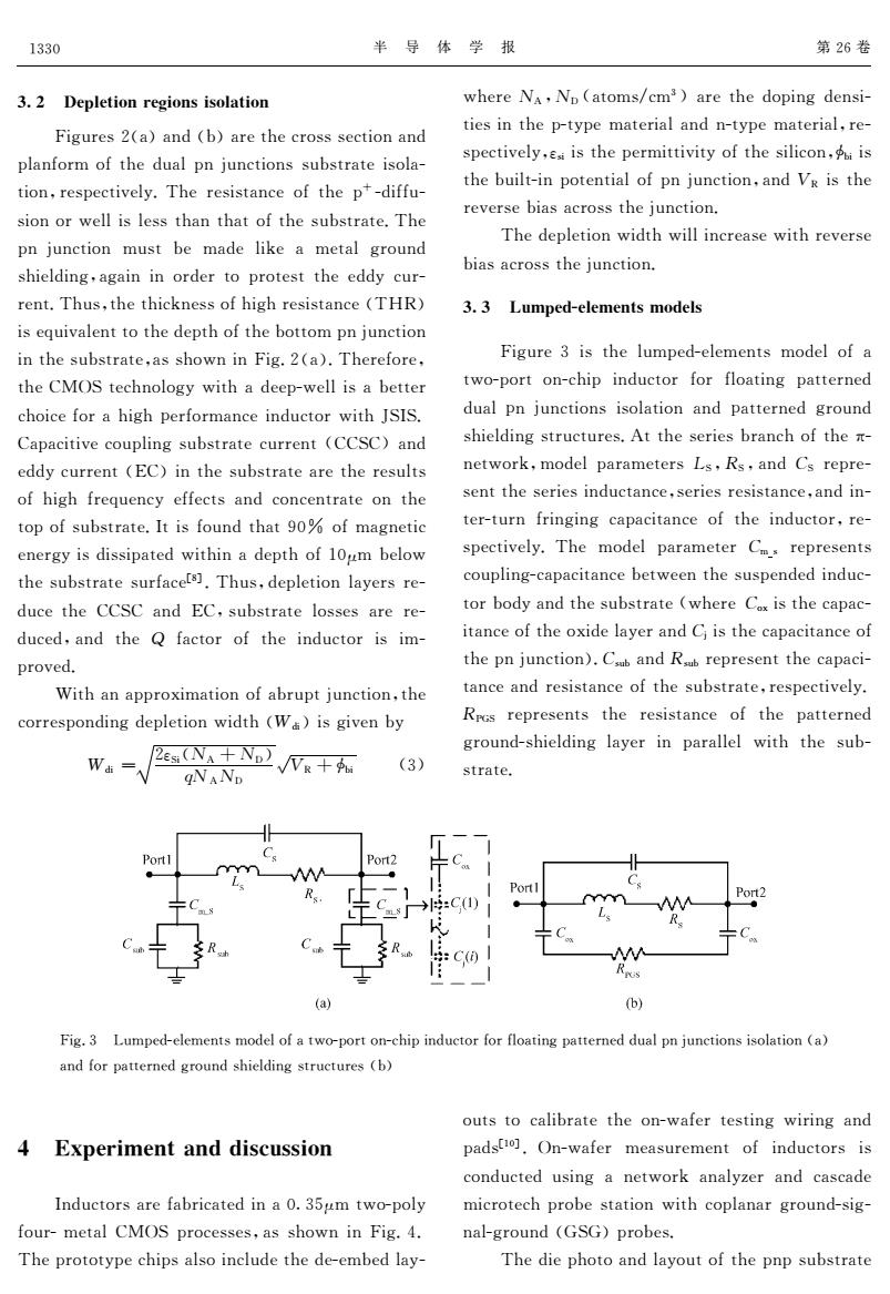
1330 半导体学报 第26卷 3.2 Depletion regions isolation where Na,Np (atoms/cm3)are the doping densi- Figures 2(a)and (b)are the cross section and ties in the p-type material and n-type material,re- spectively,e is the permittivity of the silicon,is planform of the dual pn junctions substrate isola- tion,respectively.The resistance of the pt-diffu- the built-in potential of pn junction,and Vg is the reverse bias across the junction. sion or well is less than that of the substrate.The The depletion width will increase with reverse pn junction must be made like a metal ground bias across the junction. shielding,again in order to protest the eddy cur- rent.Thus,the thickness of high resistance(THR) 3.3 Lumped-elements models is equivalent to the depth of the bottom pn junction in the substrate,as shown in Fig.2(a).Therefore, Figure 3 is the lumped-elements model of a the CMOS technology with a deep-well is a better two-port on-chip inductor for floating patterned choice for a high performance inductor with JSIS. dual pn junctions isolation and patterned ground Capacitive coupling substrate current (CCSC)and shielding structures.At the series branch of the x- eddy current(EC)in the substrate are the results network,model parameters Ls,Rs,and Cs repre- of high frequency effects and concentrate on the sent the series inductance,series resistance,and in- top of substrate.It is found that 90%of magnetic ter-turn fringing capacitance of the inductor,re- energy is dissipated within a depth of 10um below spectively.The model parameter Cm.represents the substrate surfacets.Thus,depletion layers re- coupling-capacitance between the suspended induc- duce the CCSC and EC,substrate losses are re- tor body and the substrate (where Cx is the capac- duced,and the Q factor of the inductor is im- itance of the oxide layer and C is the capacitance of proved. the pn junction).C.ub and Raub represent the capaci- With an approximation of abrupt junction,the tance and resistance of the substrate,respectively. corresponding depletion width (Wa)is given by Rros represents the resistance of the patterned 2esNA+ND√/NR+ ground-shielding layer in parallel with the sub- (3) gNAND strate. Port2 Port2 :C(1) :C(0 (a) (b) Fig.3 Lumped-elements model of a two-port on-chip inductor for floating patterned dual pn junctions isolation (a) and for patterned ground shielding structures (b) outs to calibrate the on-wafer testing wiring and 4 Experiment and discussion pads(10].On-wafer measurement of inductors is conducted using a network analyzer and cascade Inductors are fabricated in a 0.35gm two-poly microtech probe station with coplanar ground-sig- four-metal CMOS processes,as shown in Fig.4. nal-ground (GSG)probes. The prototype chips also include the de-embed lay- The die photo and layout of the pnp substrate
半 导 体 学 报 第B_卷 U;+ $>D:>?J9H@>RJ9HAJA9:C?J9H F$32.;7B!&"&),!G"&.;’4;%.(777;%’$()&), "#&)*(.0(*’4;,2&#")@2)%’$()772G7’.&’;$7(#&[ ’$()#.;7";%’$O;#6cQ4;.;7$7’&)%;(*’4;"k [,$**2[ 7$()(.T;##$7#;77’4&)’4&’(*’4;72G7’.&’;cQ4; ")@2)%’$() 027’G; 0&,;#$^;& 0;’.(2), 74$;#,$)3#&3&$)$)(.,;.’(".(’;7’’4;;,,6%2.[ .;)’cQ427#’4;’4$%^);77(*4$34.;7$7’&)%;!Q8P" $7;]2$O&#;)’’(’4;,;"’4(*’4;G(’’(0")@2)%’$() $)’4;72G7’.&’;#&774(T)$)F$3cB!&"cQ4;.;*(.;# ’4;5DR1’;%4)(#(36T$’4&,;;"[T;##$7&G;’’;. %4($%;*(.&4$34";.*(.0&)%;$),2%’(.T$’4Y1J1c 5&"&%$’$O;%(2"#$)372G7’.&’;%2..;)’!5515"&), ;,,6%2..;)’!E5"$)’4;72G7’.&’;&.;’4;.;72#’7 (*4$34*.;]2;)%6;**;%’7&),%()%;)’.&’;()’4; ’("(*72G7’.&’;cJ’$7*(2),’4&’SWg (*0&3);’$% ;);.36$7,$77$"&’;,T$’4$)&,;"’4(*AW!0G;#(T ’4;72G7’.&’;72.*&%;$C% cQ427#,;"#;’$()#&6;.7.;[ ,2%;’4; 5515 &), E5#72G7’.&’;#(77;7&.;.;[ ,2%;,#&),’4; , *&%’(.(*’4;$),2%’(.$7$0[ ".(O;,c >$’4&)&"".(/$0&’$()(*&G.2"’@2)%’$()#’4; %(..;7"(),$)3,;"#;’$()T$,’4!/,$"$73$O;)G6 /,$ S B#1$!J! WJU" , CJ!JU ,\P W+G$ !Z" T4;.;J!#JU !&’(07&%0Z"&.;’4;,("$)3,;)7$[ ’$;7$)’4;"[’6";0&’;.$&#&),)[’6";0&’;.$&##.;[ 7";%’$O;#6##7$$7’4;";.0$’’$O$’6(*’4;7$#$%()#+G$$7 ’4;G2$#’[$)"(’;)’$&#(*")@2)%’$()#&),\P$7’4; .;O;.7;G$&7&%.(77’4;@2)%’$()c Q4;,;"#;’$()T$,’4T$##$)%.;&7;T$’4.;O;.7; G$&7&%.(77’4;@2)%’$()c U;U 5LV>:>Q>H?AQ9L>:A F$32.;Z$7’4;#20";,[;#;0;)’7 0(,;#(*& ’T(["(.’()[%4$"$),2%’(.*(.*#(&’$)3 "&’’;.);, ,2&#")@2)%’$()7$7(#&’$()&),"&’’;.);,3.(2), 74$;#,$)37’.2%’2.;7c!’’4;7;.$;7G.&)%4(*’4;&[ );’T(.^#0(,;#"&.&0;’;.711#E1#&),+1 .;".;[ 7;)’’4;7;.$;7$),2%’&)%;#7;.$;7.;7$7’&)%;#&),$)[ ’;.[’2.)*.$)3$)3%&"&%$’&)%;(*’4;$),2%’(.#.;[ 7";%’$O;#6cQ4; 0(,;#"&.&0;’;. +07 .;".;7;)’7 %(2"#$)3[%&"&%$’&)%;G;’T;;)’4;727";),;,$),2%[ ’(.G(,6&),’4;72G7’.&’;!T4;.;+(/$7’4;%&"&%[ $’&)%;(*’4;(/$,;#&6;.&),+@$7’4;%&"&%$’&)%;(* ’4;")@2)%’$()"c+72G&),E72G.;".;7;)’’4;%&"&%$[ ’&)%;&),.;7$7’&)%;(*’4;72G7’.&’;#.;7";%’$O;#6c E+=1 .;".;7;)’7’4; .;7$7’&)%; (*’4; "&’’;.);, 3.(2),[74$;#,$)3#&6;.$) "&.&##;# T$’4’4;72G[ 7’.&’;c F$3cZ ?20";,[;#;0;)’70(,;#(*&’T(["(.’()[%4$"$),2%’(.*(.*#(&’$)3"&’’;.);,,2&#")@2)%’$()7$7(#&’$()!&" &),*(."&’’;.);,3.(2),74$;#,$)37’.2%’2.;7!G" W *PD>@JQ>H?CHLLJAN<AAJ9H J),2%’(.7&.;*&G.$%&’;,$)&W‘ZV!0’T(["(#6 *(2.[0;’DR1".(%;77;7#&774(T)$)F$3cXc Q4;".(’(’6";%4$"7($)%#2,;’4;,;[;0G;,#&6[ (2’7’(%&#$G.&’;’4;()[T&*;.’;7’$)3 T$.$)3&), "&,7$AW% cR)[T&*;. 0;&72.;0;)’ (*$),2%’(.7$7 %(),2%’;,27$)3&);’T(.^&):;.&),%&7%&,; 0$%.(’;%4".(G;7’&’$()T$’4%("#&)&.3.(2),[7$3[ )&#[3.(2),!=1="".(G;7c Q4;,$;"4(’(&),#&6(2’(*’4;")"72G7’.&’; AZZW
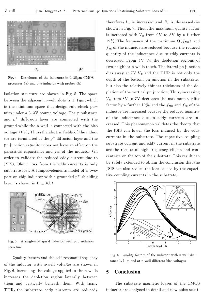
第7期 Jian Hongyan et al.:Patterned Dual pn Junctions Restraining Substrate Loss of... 1331 therefore,L,is increased and R,is decreased,as shown in Fig.7.Thus,the maximum quality factor is increased with Vg from OV to 3V by a further ■ 19%.The frequency of the maximum Q(fMQ)and fsg of the inductor are reduced because the reduced quantity of the inductance due to eddy currents is ■41级服w出■ 。国■ decreased.From 4V Vg the depletion regions of two neighbor n-wells touch.The lateral pn junction AI dies away at 7V Vg and the THR is not only the Fig.4 Die photos of the inductors in 0.35um CMOS depth of the bottom pn junction in the substrate, processes (a)and one inductor with probes (b) but also the relatively thinner thickness of the de- isolation structure are shown in Fig.5.The space pletion of the vertical pn junction.Thus,increasing between the adjacent n-well slots is 1.Ium,which V&from 3V to 7V decreases the maximum quality is the minimum space that design rule check per- factor by a further 19%and the fMo and fsk of the mits under a 3.3V source voltage.The p-substrate inductor are increased because the reduced quantity and p diffusion layer are connected with the of the inductance due to eddy currents are in- ground while the n-well is connected with the bias creased.This phenomenon validates the theory that voltage (VR).Thus,the electric fields of the induc- the JSIS can lower the loss induced by the eddy tor are terminated at the p diffusion layer and the currents in the substrate.The capacitive coupling pn junction capacitor does not have an effect on the substrate current and eddy current in the substrate parasitical capacitance and fsg of the inductor (in are the results of high frequency effects and con- order to validate the reduced eddy current due to centrate on the top of the substrate.This result can JSIS).Ohmic loss from the eddy currents is only be safely extended to obtain the conclusion that the substrate loss.A lumped-elements model of a two- JSIS can also reduce the loss caused by the capaci- port on-chip inductor with a grounded p shielding tive coupling currents in the substrate. layer is shown in Fig.3(b). 3V 4 pi业 T下 -C 8 日 0. OV T15 0.1 4V 11 11.5 12 Fig.5 A single-end spiral inductor with pnp isolation 4 6 8 10 12 structure Frequency/GHz Fig.6 Quality factors of the inductor with n-well dis- Quality factors and the self-resonant frequency tance 1.lum and at n-well different bias voltages of the inductor with n-well voltages are shown in Fig.6.Increasing the voltage applied to the n-wells 5 Conclusion increases the depletion region laterally between them and vertically beneath them.With rising The substrate magnetic losses of the CMOS THR,the substrate eddy currents are reduced; inductor are analyzed in detail and new substrate i-
第M期 Y$&)8()36&)*M#8T! +&’’;.);,U2&#")Y2)%’$()7P;7’.&$)$)312G7’.&’;?(77(*" F$3cX U$;"4(’(7(*’4;$),2%’(.7$)W‘ZV!0 5DR1 ".(%;77;7#&$&),();$),2%’(.T$’4".(G;7#G$ $7(#&’$()7’.2%’2.;&.;74(T)$)F$3cVcQ4;7"&%; G;’T;;)’4;&,@&%;)’)[T;##7#(’7$7A‘A!0%T4$%4 $7’4;0$)$0207"&%;’4&’,;7$3).2#;%4;%^";.[ 0$’72),;.&Z‘ZH7(2.%;O(#’&3;cQ4;"[72G7’.&’; &), "k ,$**27$() #&6;. &.; %());%’;, T$’4 ’4; 3.(2),T4$#;’4;)[T;##$7%());%’;,T$’4’4;G$&7 O(#’&3;#\P$cQ427%’4;;#;%’.$%*$;#,7(*’4;$),2%[ ’(.&.;’;.0$)&’;,&’’4;"k ,$**27$()#&6;.&),’4; ")@2)%’$()%&"&%$’(.,(;7)(’4&O;&);**;%’()’4; "&.&7$’$%&#%&"&%$’&)%;&),=1P (*’4;$),2%’(. #$) (.,;.’(O&#$,&’;’4;.;,2%;,;,,6%2..;)’,2;’( Y1J1$cR40$%#(77*.(0’4;;,,6%2..;)’7$7()#6 72G7’.&’;#(77c!#20";,[;#;0;)’70(,;#(*&’T([ "(.’()[%4$"$),2%’(.T$’4&3.(2),;,"k 74$;#,$)3 #&6;.$774(T)$)F$3cZ#G$c F$3cV !7$)3#;[;),7"$.&#$),2%’(.T$’4")"$7(#&’$() 7’.2%’2.; $’4 .$7$)3 Q8P%’4;72G7’.&’;;,,6 %2..;)’7&.;.;,2%;,& ’4;.;*(.;%17$7$)%.;&7;,&),E7$7,;%.;&7;,%&7 74(T)$)F$3cMcQ427%’4;0&/$020]2&#$’6*&%’(. $7$)%.;&7;,T$’4\P *.(0WH’(ZH G6&*2.’4;. ASgcQ4;*.;]2;)%6(*’4;0&/$020,#=D< $&), =1P(*’4;$),2%’(.&.;.;,2%;,G;%&27;’4;.;,2%;, ]2&)’$’6(*’4;$),2%’&)%;,2;’(;,,6%2..;)’7$7 ,;%.;&7;,cF.(0 XH \P ’4;,;"#;’$().;3$()7(* ’T();$34G(.)[T;##7’(2%4cQ4;#&’;.&#")@2)%’$() ,$;7&T&6&’MH\P &),’4;Q8P$7)(’()#6’4; ,;"’4(*’4;G(’’(0")@2)%’$()$)’4;72G7’.&’;% G2’(’4;.;#&’$O;#6’4$));.’4$%^);77(*’4;,;[ "#;’$()(*’4;O;.’$%&#")@2)%’$()cQ427%$)%.;&7$)3 \P*.(0ZH’(MH,;%.;&7;7’4;0&/$020]2&#$’6 *&%’(.G6&*2.’4;.ASg&),’4;=D<&),=1P(*’4; $),2%’(.&.;$)%.;&7;,G;%&27;’4;.;,2%;,]2&)’$’6 (*’4;$),2%’&)%; ,2;’( ;,,6 %2..;)’7&.;$)[ %.;&7;,cQ4$7"4;)(0;)()O&#$,&’;7’4;’4;(.6’4&’ ’4;Y1J1%&)#(T;.’4;#(77$),2%;,G6’4;;,,6 %2..;)’7$)’4;72G7’.&’;cQ4;%&"&%$’$O;%(2"#$)3 72G7’.&’;%2..;)’&),;,,6%2..;)’$)’4;72G7’.&’; &.;’4;.;72#’7(*4$34*.;]2;)%6;**;%’7&),%()[ %;)’.&’;()’4;’("(*’4;72G7’.&’;cQ4$7.;72#’%&) G;7&*;#6;/’;),;,’((G’&$)’4;%()%#27$()’4&’’4; Y1J1%&)(.;,2%;’4;#(77%&27;,G6’4;%&"&%$[ ’$O;%(2"#$)3%2..;)’7$)’4;72G7’.&’;c F$3c_ <2&#$’6*&%’(.7(*’4;$),2%’(.T$’4)[T;##,$7[ ’&)%;A‘A!0&),&’)[T;##,$**;.;)’G$&7O(#’&3;7 / 09HN:<AJ9H Q4;72G7’.&’; 0&3);’$%#(77;7(*’4;5DR1 $),2%’(.&.;&):;,$),;’&$#&),);T72G7’.&’;$[ AZZA
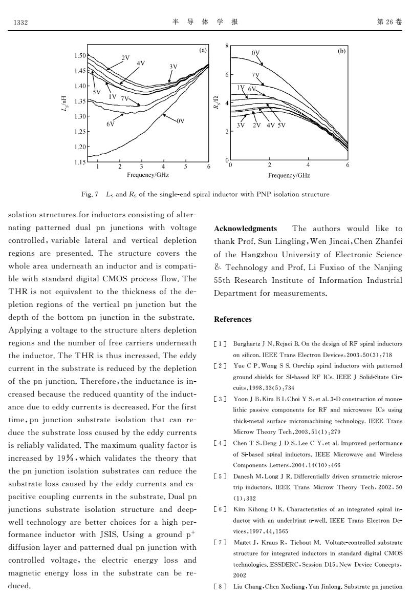
1332 半导体学报 第26卷 (a) (b) 1.50 4 1.45 1.40 1.35 1.30 6V 1.25 1.20 1.15 3 4 4 Frequency/GHz Frequency/GHz Fig.7 Ls and Rs of the single-end spiral inductor with PNP isolation structure solation structures for inductors consisting of alter- nating patterned dual pn junctions with voltage Acknowledgments The authors would like to controlled,variable lateral and vertical depletion thank Prof.Sun Lingling,Wen Jincai,Chen Zhanfei regions are presented.The structure covers the of the Hangzhou University of Electronic Science whole area underneath an inductor and is compati- &Technology and Prof.Li Fuxiao of the Nanjing ble with standard digital CMOS process flow.The 55th Research Institute of Information Industrial THR is not equivalent to the thickness of the de- Department for measurements. pletion regions of the vertical pn junction but the depth of the bottom pn junction in the substrate. References Applying a voltage to the structure alters depletion regions and the number of free carriers underneath [1]Burghartz J N,Rejaei B.On the design of RF spiral inductors the inductor.The THR is thus increased.The eddy on silicon.IEEE Trans Electron Devices,2003.50(3):718 current in the substrate is reduced by the depletion [2 Yue C P.Wong SS.On-chip spiral inductors with patterned of the pn junction.Therefore,the inductance is in- ground shields for SI-based RF ICs.IEEE J Solid-State Cir- cuits,1998,33(5):734 creased because the reduced quantity of the induct- [3]Yoon J B.Kim BI.Choi Y S.et al.3-D construction of mono- ance due to eddy currents is decreased.For the first lithic passive components for RF and microwave ICs using time,pn junction substrate isolation that can re- thick-metal surface micromachining technology.IEEE Trans duce the substrate loss caused by the eddy currents Microw Theory Tech.2003.51(1):279 is reliably validated.The maximum quality factor is [4]Chen T S.Deng J D S.Lee C Y.et al.Improved performance increased by 19%,which validates the theory that of Si-based spiral inductors.IEEE Microwave and Wireless Components Letters.2004.14(10):466 the pn junction isolation substrates can reduce the [5]Danesh M.Long J R.Differentially driven symmetric micros- substrate loss caused by the eddy currents and ca- trip induetors.IEEE Trans Microw Theory Tech.2002.50 pacitive coupling currents in the substrate.Dual pn (1):332 junctions substrate isolation structure and deep- [6]Kim Kihong O K.Characteristics of an integrated spiral in- well technology are better choices for a high per- ductor with an underlying n-well.IEEE Trans Electron De- formance inductor with JSIS.Using a ground p vices,1997,44:1565 diffusion layer and patterned dual pn junction with [7]Maget J,Kraus R.Tiebout M.Voltage-controlled substrate structure for integrated inductors in standard digital CMOS controlled voltage,the electric energy loss and technologies.ESSDERC,Session D15:New Device Concepts. magnetic energy loss in the substrate can be re- 2002 duced. [8]Liu Chang.Chen Xueliang.Yan Jinlong.Substrate pn junction
半 导 体 学 报 第B_卷 F$3cM 11&),E1(*’4;7$)3#;[;),7"$.&#$),2%’(.T$’4+N+$7(#&’$()7’.2%’2.; 7(#&’$()7’.2%’2.;7*(.$),2%’(.7%()7$7’$)3(*&#’;.[ )&’$)3"&’’;.);, ,2&#")@2)%’$()7 T$’4 O(#’&3; %()’.(##;,!O&.$&G#;#&’;.&#&), O;.’$%&#,;"#;’$() .;3$()7&.; ".;7;)’;,cQ4;7’.2%’2.;%(O;.7’4; T4(#;&.;&2),;.);&’4&)$),2%’(.&),$7%(0"&’$[ G#;T$’47’&),&.,,$3$’DR1".(%;77*#(TcQ4; Q8P$7)(’;]2$O&#;)’’(’4;’4$%^);77(*’4;,;[ "#;’$().;3$()7(*’4;O;.’$%&#")@2)%’$()G2’’4; ,;"’4(*’4;G(’’(0")@2)%’$()$)’4;72G7’.&’;c !""#6$)3&O(#’&3;’(’4;7’.2%’2.;&#’;.7,;"#;’$() .;3$()7&),’4;)20G;.(**.;;%&..$;.72),;.);&’4 ’4;$),2%’(.cQ4;Q8P$7’427$)%.;&7;,cQ4;;,,6 %2..;)’$)’4;72G7’.&’;$7.;,2%;,G6’4;,;"#;’$() (*’4;")@2)%’$()cQ4;.;*(.;!’4;$),2%’&)%;$7$)[ %.;&7;,G;%&27;’4;.;,2%;,]2&)’$’6(*’4;$),2%’[ &)%;,2;’(;,,6%2..;)’7$7,;%.;&7;,cF(.’4;*$.7’ ’$0;!")@2)%’$()72G7’.&’;$7(#&’$()’4&’%&).;[ ,2%;’4;72G7’.&’;#(77%&27;,G6’4;;,,6%2..;)’7 $7.;#$&G#6O&#$,&’;,cQ4;0&/$020]2&#$’6*&%’(.$7 $)%.;&7;,G6ASg!T4$%4O&#$,&’;7’4;’4;(.6’4&’ ’4;")@2)%’$()$7(#&’$()72G7’.&’;7%&).;,2%;’4; 72G7’.&’;#(77%&27;,G6’4;;,,6%2..;)’7&),%&[ "&%$’$O;%(2"#$)3%2..;)’7$)’4;72G7’.&’;cU2&#") @2)%’$()772G7’.&’;$7(#&’$()7’.2%’2.;&), ,;;"[ T;##’;%4)(#(36&.;G;’’;.%4($%;7*(.&4$34";.[ *(.0&)%;$),2%’(.T$’4Y1J1cb7$)3&3.(2),"k ,$**27$()#&6;.&),"&’’;.);,,2&#")@2)%’$()T$’4 %()’.(##;, O(#’&3;!’4; ;#;%’.$% ;);.36 #(77 &), 0&3);’$%;);.36#(77$)’4;72G7’.&’;%&)G;.;[ ,2%;,c "N^H9T:>LRQ>H?A Q4; &2’4(.7 T(2#, #$^; ’( ’4&)^+.(*c12)?$)3#$)3!>;)Y$)%&$!54;)L4&)*;$ (*’4; 8&)3:4(2 b)$O;.7$’6(*E#;%’.()$%1%$;)%; r Q;%4)(#(36&),+.(*c?$F2/$&((*’4;N&)@$)3 VV’4 P;7;&.%4J)7’$’2’;(*J)*(.0&’$()J),27’.$&# U;"&.’0;)’*(.0;&72.;0;)’7c 4>M>@>HN>A "A# I2.34&.’:YN!P;@&;$IcR)’4;,;7$3)(*PF7"$.&#$),2%’(.7 ()7$#$%()cJEEEQ.&)7E#;%’.()U;O$%;7!BWWZ!VW$Z%&MAC "B# 92;5+!>()311cR)[%4$"7"$.&#$),2%’(.7T$’4"&’’;.);, 3.(2),74$;#,7*(.1J[G&7;,PFJ57cJEEEY1(#$,[1’&’;5$.[ %2$’7!ASSC!ZZ$V%&MZX "Z# 9(()YI!\$0IJ!54($91!;’&#cZ[U%()7’.2%’$()(*0()([ #$’4$%"&77$O;%(0"();)’7*(.PF&), 0$%.(T&O;J5727$)3 ’4$%^[0;’H.*&%;0$%.(0&%4$)$)3’;%4)(#(36cJEEE Q.&)7 D$%.(TQ4;(.6Q;%4!BWWZ!VA$A%&BMS "X# 54;)Q1!U;)3YU1!?;;59!;’&#cJ0".(O;,";.*(.0&)%; (*1$[G&7;,7"$.&#$),2%’(.7cJEEE D$%.(T&O;&), >$.;#;77 5(0"();)’7?;’’;.7!BWWX!AX$AW%&X__ "V# U&);74D!?()3YPcU$**;.;)’$&##6,.$O;)7600;’.$%0$%.(7[ ’.$"$),2%’(.7cJEEE Q.&)7 D$%.(T Q4;(.6 Q;%4!BWWB!VW $A%&ZZB "_# \$0 \$4()3R \c54&.&%’;.$7’$%7(*&)$)’;3.&’;,7"$.&#$)[ ,2%’(.T$’4&)2),;.#6$)3)[T;##cJEEE Q.&)7E#;%’.()U;[ O$%;7!ASSM!XX&AV_V "M# D&3;’Y!\.&27P!Q$;G(2’DcH(#’&3;[%()’.(##;,72G7’.&’; 7’.2%’2.;*(.$)’;3.&’;,$),2%’(.7$)7’&),&.,,$3$’DR1 ’;%4)(#(3$;7cE11UEP5!1;77$()UAV&N;T U;O$%;5()%;"’7! BWWB "C# ?$254&)3!54;)K2;#$&)3!9&)Y$)#()3c12G7’.&’;")@2)%’$() AZZB

第7期 Jian Hongyan et al.Patterned Dual pn Junctions Restraining Substrate Loss of... 1333 isolation for RF integrated inductors on silicon.Chinese Jour- crow Theory Techn.2004,52(5):1375 nal of Semiconductors.2001.22(12):1486 [10]Maget J.PhD Dissertation.University of Bundeswehr.Neu- [9]Chang C A.Tseng S P.Yi J C,et al.Characterization of spiral biberg.Germany.2002 inductors with patterned floating structures.IEEE Trans Mi- 放射状双pn结抑制片上电感衬底损耗* 营洪彦唐珏唐长文何捷闵昊 (复旦大学专用集成电路与系统国家重点实验室,上海200433) 摘要:使用标准CMOS工艺,在放射状的n阱上面扩散p+,使垂直和水平方向形成双pn结,将此结放在电感的底 部用来抑制衬底损耗.提出并实验证明了该结构形成的高阻区厚度不是垂直p结耗尽层的厚度,而是最低层的pn 结的深度.首次通过接地的p+扩散层屏敲电感到衬底电场,水平和垂直p结耗尽层厚度随着pm结反向偏压升高 改变村底有效的高阻区厚度,电感品质因数跟随高阻区厚度升降,有效地证明了p结衬底隔离可以降低电感的村 底电流造成的损耗 关键词:片上电感;放射状双p结;涡流;衬底损耗 EEACC:2140:2530B:2550F 中图分类号:TM55 文献标识码:A 文章编号:0253-4177(2005)07-1328-06 *上海市科委(批准号:037062019)及上海应用材料研究生发展基金(批准号:0425)资助项目 营洪彦男,博士研究生,研究方向包括片上电感和片上天线的优化设计,射频电路设计,例如低噪声放大器、混频器和压控振荡器等以及射 频识别天线设计.Email:hyjian@fudan.edu.cm 2004-12-09收到,2005-01-24定稿 ©2005中国电子学会
第M期 Y$&)8()36&)*M#8T! +&’’;.);,U2&#")Y2)%’$()7P;7’.&$)$)312G7’.&’;?(77(*" $7(#&’$()*(.PF$)’;3.&’;,$),2%’(.7()7$#$%()c54$);7;Y(2.[ )&#(*1;0$%(),2%’(.7#BWWA#BB$AB%!AXC_ &S’ 54&)35!#Q7;)31+#9$Y5#;’&#c54&.&%’;.$:&’$()(*7"$.&# $),2%’(.7T$’4"&’’;.);,*#(&’$)37’.2%’2.;7cJEEEQ.&)7D$[ %.(TQ4;(.6Q;%4)#BWWX#VB$V%!AZMV &AW’ D&3;’Yc+4U U$77;.’&’$()cb)$O;.7$’6(*I2),;7T;4.#N;2[ G$G;.3#=;.0&)6#BWWB 放射状双DH结抑制片上电感衬底损耗# 菅洪彦 唐 珏 唐长文 何 捷 闵 昊 $复旦大学专用集成电路与系统国家重点实验室#上海 BWWXZZ% 摘要!使用标准 5DR1工艺#在放射状的)阱上面扩散"k #使垂直和水平方向形成双")结#将此结放在电感的底 部用来抑制衬底损耗c提出并实验证明了该结构形成的高阻区厚度不是垂直")结耗尽层的厚度#而是最低层的") 结的深度c首次通过接地的"k 扩散层屏蔽电感到衬底电场#水平和垂直")结耗尽层厚度随着")结反向偏压升高 改变衬底有效的高阻区厚度#电感品质因数跟随高阻区厚度升降#有效地证明了")结衬底隔离可以降低电感的衬 底电流造成的损耗c 关键词!片上电感(放射状双")结(涡流(衬底损耗 **"00!BAXW(BVZWI(BVVWF 中图分类号!QDVV 文献标识码!! 文章编号!WBVZ[XAMM"BWWV#WM[AZBC[W_ #上海市科委$批准号!WZMW_BWAS%及上海应用材料研究生发展基金$批准号!WXBV%资助项目 菅洪彦 男#博士研究生#研究方向包括片上电感和片上天线的优化设计#射频电路设计#例如低噪声放大器)混频器和压控振荡器等以及射 频识别天线设计cE0&$#!46@$&)"*2,&)c;,2c%) BWWX[AB[WS收到#BWWV[WA[BX定稿 #BWWV 中国电子学会 AZZZ