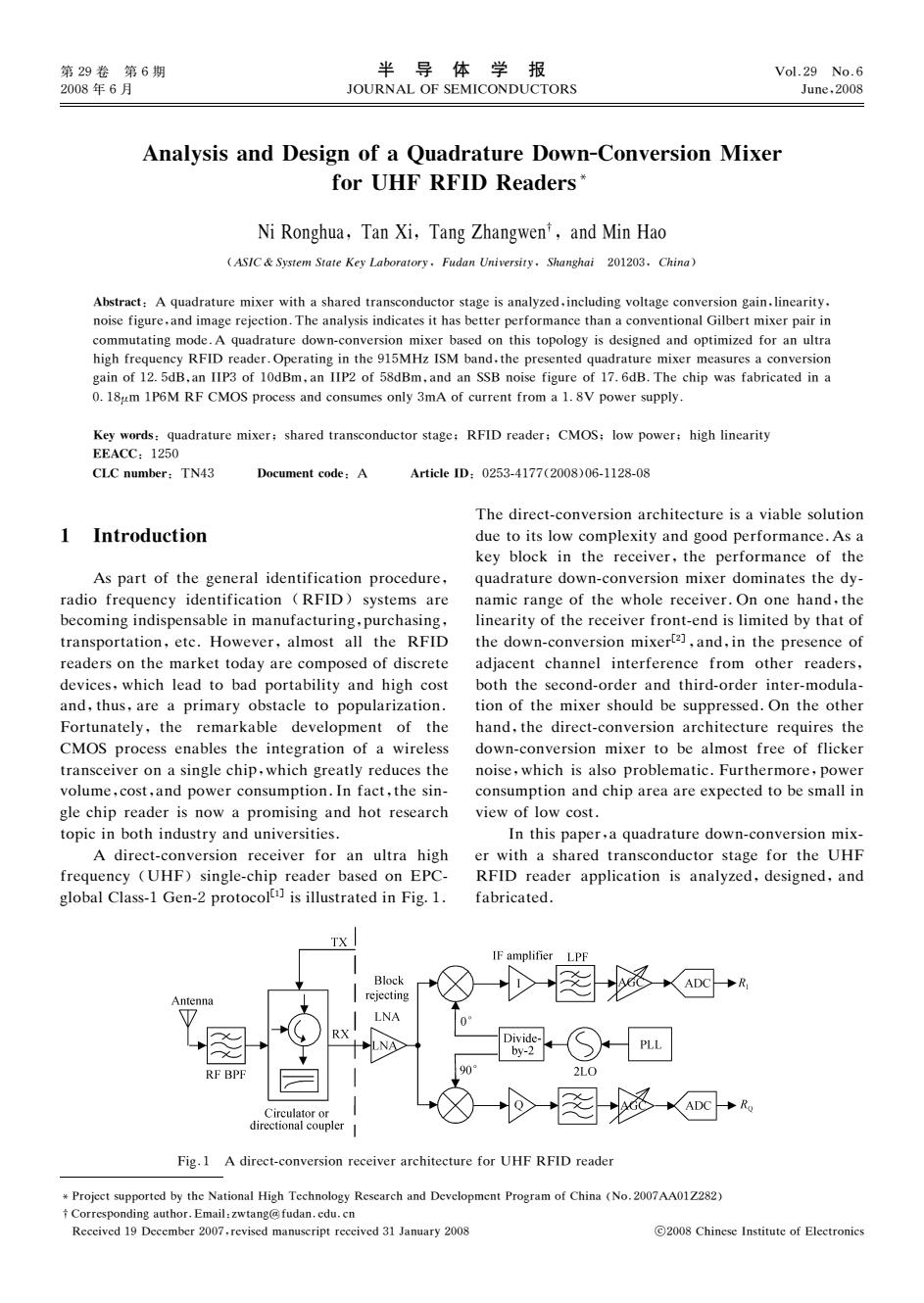
第29卷第6期 半导体学报 Vol.29 No.6 2008年6月 JOURNAL OF SEMICONDUCTORS June,2008 Analysis and Design of a Quadrature Down-Conversion Mixer for UHF RFID Readers* Ni Ronghua,Tan Xi,Tang Zhangwen',and Min Hao (ASIC System State Key Laboratory.Fudan University.Shanghai 201203.China) Abstract:A quadrature mixer with a shared transconductor stage is analyzed,including voltage conversion gain.linearity. noise figure,and image rejection.The analysis indicates it has better performance than a conventional Gilbert mixer pair in commutating mode.A quadrature down-conversion mixer based on this topology is designed and optimized for an ultra high frequency RFID reader.Operating in the 915MHz ISM band.the presented quadrature mixer measures a conversion gain of 12.5dB,an IIP3 of 10dBm,an IIP2 of 58dBm,and an SSB noise figure of 17.6dB.The chip was fabricated in a 0.18um 1P6M RF CMOS process and consumes only 3mA of current from a 1.8V power supply. Key words:quadrature mixer;shared transconductor stage:RFID reader:CMOS:low power:high linearity EEACC:1250 CLC number:TN43 Document code:A Article ID:0253-4177(2008)06-1128-08 The direct-conversion architecture is a viable solution 1 Introduction due to its low complexity and good performance.As a key block in the receiver,the performance of the As part of the general identification procedure,quadrature down-conversion mixer dominates the dy- radio frequency identification (RFID)systems are namic range of the whole receiver.On one hand,the becoming indispensable in manufacturing,purchasing,linearity of the receiver front-end is limited by that of transportation,etc.However,almost all the RFID the down-conversion mixer[2],and,in the presence of readers on the market today are composed of discrete adjacent channel interference from other readers, devices,which lead to bad portability and high cost both the second-order and third-order inter-modula- and,thus,are a primary obstacle to popularization.tion of the mixer should be suppressed.On the other Fortunately,the remarkable development of the hand,the direct-conversion architecture requires the CMOS process enables the integration of a wireless down-conversion mixer to be almost free of flicker transceiver on a single chip,which greatly reduces the noise,which is also problematic.Furthermore,power volume,cost,and power consumption.In fact,the sin-consumption and chip area are expected to be small in gle chip reader is now a promising and hot research view of low cost. topic in both industry and universities. In this paper,a quadrature down-conversion mix- A direct-conversion receiver for an ultra high er with a shared transconductor stage for the UHF frequency (UHF)single-chip reader based on EPC-RFID reader application is analyzed,designed,and global Class-1 Gen-2 is illustrated in Fig.1.fabricated. TX IF amplifier LPF Block D图 ADC R Antenna rejecting LNA RX Divide LNA by-2 PLL RF BPF 90° 2LO Circulator or 之 408 ADC Ro directional coupler Fig.1 A direct-conversion receiver architecture for UHF RFID reader Projcct supported by the National High Technology Research and Development Program of China (No.2007AA01Z282) t Corresponding author.Email:zwtang@fudan.edu.cn Received 19 December 2007.revised manuscript received 31 January 2008 2008 Chinese Institute of Electronics
第29卷 第6期 2008年6月 半 导 体 学 报 犑犗犝犚犖犃犔犗犉犛犈犕犐犆犗犖犇犝犆犜犗犚犛 犞狅犾.29 犖狅.6 犑狌狀犲,2008 犘狉狅犼犲犮狋狊狌狆狆狅狉狋犲犱犫狔狋犺犲犖犪狋犻狅狀犪犾犎犻犵犺犜犲犮犺狀狅犾狅犵狔犚犲狊犲犪狉犮犺犪狀犱犇犲狏犲犾狅狆犿犲狀狋犘狉狅犵狉犪犿狅犳犆犺犻狀犪(犖狅.2007犃犃01犣282) 犆狅狉狉犲狊狆狅狀犱犻狀犵犪狌狋犺狅狉.犈犿犪犻犾:狕狑狋犪狀犵@犳狌犱犪狀.犲犱狌.犮狀 犚犲犮犲犻狏犲犱19犇犲犮犲犿犫犲狉2007,狉犲狏犻狊犲犱犿犪狀狌狊犮狉犻狆狋狉犲犮犲犻狏犲犱31犑犪狀狌犪狉狔2008 2008犆犺犻狀犲狊犲犐狀狊狋犻狋狌狋犲狅犳犈犾犲犮狋狉狅狀犻犮狊 犃狀犪犾狔狊犻狊犪狀犱犇犲狊犻犵狀狅犳犪犙狌犪犱狉犪狋狌狉犲犇狅狑狀犆狅狀狏犲狉狊犻狅狀犕犻狓犲狉 犳狅狉犝犎犉犚犉犐犇犚犲犪犱犲狉狊 犖犻犚狅狀犵犺狌犪,犜犪狀犡犻,犜犪狀犵犣犺犪狀犵狑犲狀,犪狀犱犕犻狀犎犪狅 (犃犛犐犆牔犛狔狊狋犲犿犛狋犪狋犲犓犲狔犔犪犫狅狉犪狋狅狉狔,犉狌犱犪狀犝狀犻狏犲狉狊犻狋狔,犛犺犪狀犵犺犪犻 201203,犆犺犻狀犪) 犃犫狊狋狉犪犮狋:犃狇狌犪犱狉犪狋狌狉犲犿犻狓犲狉狑犻狋犺犪狊犺犪狉犲犱狋狉犪狀狊犮狅狀犱狌犮狋狅狉狊狋犪犵犲犻狊犪狀犪犾狔狕犲犱,犻狀犮犾狌犱犻狀犵狏狅犾狋犪犵犲犮狅狀狏犲狉狊犻狅狀犵犪犻狀,犾犻狀犲犪狉犻狋狔, 狀狅犻狊犲犳犻犵狌狉犲,犪狀犱犻犿犪犵犲狉犲犼犲犮狋犻狅狀.犜犺犲犪狀犪犾狔狊犻狊犻狀犱犻犮犪狋犲狊犻狋犺犪狊犫犲狋狋犲狉狆犲狉犳狅狉犿犪狀犮犲狋犺犪狀犪犮狅狀狏犲狀狋犻狅狀犪犾犌犻犾犫犲狉狋犿犻狓犲狉狆犪犻狉犻狀 犮狅犿犿狌狋犪狋犻狀犵犿狅犱犲.犃狇狌犪犱狉犪狋狌狉犲犱狅狑狀犮狅狀狏犲狉狊犻狅狀 犿犻狓犲狉犫犪狊犲犱狅狀狋犺犻狊狋狅狆狅犾狅犵狔犻狊犱犲狊犻犵狀犲犱犪狀犱狅狆狋犻犿犻狕犲犱犳狅狉犪狀狌犾狋狉犪 犺犻犵犺犳狉犲狇狌犲狀犮狔犚犉犐犇狉犲犪犱犲狉.犗狆犲狉犪狋犻狀犵犻狀狋犺犲915犕犎狕犐犛犕犫犪狀犱,狋犺犲狆狉犲狊犲狀狋犲犱狇狌犪犱狉犪狋狌狉犲犿犻狓犲狉犿犲犪狊狌狉犲狊犪犮狅狀狏犲狉狊犻狅狀 犵犪犻狀狅犳125犱犅,犪狀犐犐犘3狅犳10犱犅犿,犪狀犐犐犘2狅犳58犱犅犿,犪狀犱犪狀犛犛犅狀狅犻狊犲犳犻犵狌狉犲狅犳176犱犅.犜犺犲犮犺犻狆狑犪狊犳犪犫狉犻犮犪狋犲犱犻狀犪 018μ犿1犘6犕 犚犉犆犕犗犛狆狉狅犮犲狊狊犪狀犱犮狅狀狊狌犿犲狊狅狀犾狔3犿犃狅犳犮狌狉狉犲狀狋犳狉狅犿犪18犞狆狅狑犲狉狊狌狆狆犾狔. 犓犲狔狑狅狉犱狊:狇狌犪犱狉犪狋狌狉犲犿犻狓犲狉;狊犺犪狉犲犱狋狉犪狀狊犮狅狀犱狌犮狋狅狉狊狋犪犵犲;犚犉犐犇狉犲犪犱犲狉;犆犕犗犛;犾狅狑狆狅狑犲狉;犺犻犵犺犾犻狀犲犪狉犻狋狔 犈犈犃犆犆:1250 犆犔犆狀狌犿犫犲狉:犜犖43 犇狅犮狌犿犲狀狋犮狅犱犲:犃 犃狉狋犻犮犾犲犐犇:02534177(2008)06112808 1 犐狀狋狉狅犱狌犮狋犻狅狀 犃狊狆犪狉狋狅犳狋犺犲犵犲狀犲狉犪犾犻犱犲狀狋犻犳犻犮犪狋犻狅狀狆狉狅犮犲犱狌狉犲, 狉犪犱犻狅犳狉犲狇狌犲狀犮狔犻犱犲狀狋犻犳犻犮犪狋犻狅狀 (犚犉犐犇)狊狔狊狋犲犿狊犪狉犲 犫犲犮狅犿犻狀犵犻狀犱犻狊狆犲狀狊犪犫犾犲犻狀犿犪狀狌犳犪犮狋狌狉犻狀犵,狆狌狉犮犺犪狊犻狀犵, 狋狉犪狀狊狆狅狉狋犪狋犻狅狀,犲狋犮.犎狅狑犲狏犲狉,犪犾犿狅狊狋犪犾犾狋犺犲 犚犉犐犇 狉犲犪犱犲狉狊狅狀狋犺犲犿犪狉犽犲狋狋狅犱犪狔犪狉犲犮狅犿狆狅狊犲犱狅犳犱犻狊犮狉犲狋犲 犱犲狏犻犮犲狊,狑犺犻犮犺犾犲犪犱狋狅犫犪犱狆狅狉狋犪犫犻犾犻狋狔犪狀犱犺犻犵犺犮狅狊狋 犪狀犱,狋犺狌狊,犪狉犲犪狆狉犻犿犪狉狔狅犫狊狋犪犮犾犲狋狅狆狅狆狌犾犪狉犻狕犪狋犻狅狀. 犉狅狉狋狌狀犪狋犲犾狔,狋犺犲 狉犲犿犪狉犽犪犫犾犲 犱犲狏犲犾狅狆犿犲狀狋 狅犳 狋犺犲 犆犕犗犛狆狉狅犮犲狊狊犲狀犪犫犾犲狊狋犺犲犻狀狋犲犵狉犪狋犻狅狀狅犳犪 狑犻狉犲犾犲狊狊 狋狉犪狀狊犮犲犻狏犲狉狅狀犪狊犻狀犵犾犲犮犺犻狆,狑犺犻犮犺犵狉犲犪狋犾狔狉犲犱狌犮犲狊狋犺犲 狏狅犾狌犿犲,犮狅狊狋,犪狀犱狆狅狑犲狉犮狅狀狊狌犿狆狋犻狅狀.犐狀犳犪犮狋,狋犺犲狊犻狀 犵犾犲犮犺犻狆狉犲犪犱犲狉犻狊狀狅狑犪狆狉狅犿犻狊犻狀犵犪狀犱犺狅狋狉犲狊犲犪狉犮犺 狋狅狆犻犮犻狀犫狅狋犺犻狀犱狌狊狋狉狔犪狀犱狌狀犻狏犲狉狊犻狋犻犲狊. 犃 犱犻狉犲犮狋犮狅狀狏犲狉狊犻狅狀狉犲犮犲犻狏犲狉犳狅狉犪狀 狌犾狋狉犪 犺犻犵犺 犳狉犲狇狌犲狀犮狔 (犝犎犉)狊犻狀犵犾犲犮犺犻狆狉犲犪犱犲狉犫犪狊犲犱狅狀犈犘犆 犵犾狅犫犪犾犆犾犪狊狊1犌犲狀2狆狉狅狋狅犮狅犾[1] 犻狊犻犾犾狌狊狋狉犪狋犲犱犻狀犉犻犵1. 犜犺犲犱犻狉犲犮狋犮狅狀狏犲狉狊犻狅狀犪狉犮犺犻狋犲犮狋狌狉犲犻狊犪狏犻犪犫犾犲狊狅犾狌狋犻狅狀 犱狌犲狋狅犻狋狊犾狅狑犮狅犿狆犾犲狓犻狋狔犪狀犱犵狅狅犱狆犲狉犳狅狉犿犪狀犮犲.犃狊犪 犽犲狔犫犾狅犮犽犻狀狋犺犲狉犲犮犲犻狏犲狉,狋犺犲 狆犲狉犳狅狉犿犪狀犮犲 狅犳狋犺犲 狇狌犪犱狉犪狋狌狉犲犱狅狑狀犮狅狀狏犲狉狊犻狅狀犿犻狓犲狉犱狅犿犻狀犪狋犲狊狋犺犲犱狔 狀犪犿犻犮狉犪狀犵犲狅犳狋犺犲狑犺狅犾犲狉犲犮犲犻狏犲狉.犗狀狅狀犲犺犪狀犱,狋犺犲 犾犻狀犲犪狉犻狋狔狅犳狋犺犲狉犲犮犲犻狏犲狉犳狉狅狀狋犲狀犱犻狊犾犻犿犻狋犲犱犫狔狋犺犪狋狅犳 狋犺犲犱狅狑狀犮狅狀狏犲狉狊犻狅狀犿犻狓犲狉[2],犪狀犱,犻狀狋犺犲狆狉犲狊犲狀犮犲狅犳 犪犱犼犪犮犲狀狋犮犺犪狀狀犲犾犻狀狋犲狉犳犲狉犲狀犮犲 犳狉狅犿 狅狋犺犲狉狉犲犪犱犲狉狊, 犫狅狋犺狋犺犲狊犲犮狅狀犱狅狉犱犲狉犪狀犱狋犺犻狉犱狅狉犱犲狉犻狀狋犲狉犿狅犱狌犾犪 狋犻狅狀狅犳狋犺犲犿犻狓犲狉狊犺狅狌犾犱犫犲狊狌狆狆狉犲狊狊犲犱.犗狀狋犺犲狅狋犺犲狉 犺犪狀犱,狋犺犲犱犻狉犲犮狋犮狅狀狏犲狉狊犻狅狀犪狉犮犺犻狋犲犮狋狌狉犲狉犲狇狌犻狉犲狊狋犺犲 犱狅狑狀犮狅狀狏犲狉狊犻狅狀 犿犻狓犲狉狋狅犫犲犪犾犿狅狊狋犳狉犲犲狅犳犳犾犻犮犽犲狉 狀狅犻狊犲,狑犺犻犮犺犻狊犪犾狊狅狆狉狅犫犾犲犿犪狋犻犮.犉狌狉狋犺犲狉犿狅狉犲,狆狅狑犲狉 犮狅狀狊狌犿狆狋犻狅狀犪狀犱犮犺犻狆犪狉犲犪犪狉犲犲狓狆犲犮狋犲犱狋狅犫犲狊犿犪犾犾犻狀 狏犻犲狑狅犳犾狅狑犮狅狊狋. 犐狀狋犺犻狊狆犪狆犲狉,犪狇狌犪犱狉犪狋狌狉犲犱狅狑狀犮狅狀狏犲狉狊犻狅狀犿犻狓 犲狉狑犻狋犺犪狊犺犪狉犲犱狋狉犪狀狊犮狅狀犱狌犮狋狅狉狊狋犪犵犲犳狅狉狋犺犲 犝犎犉 犚犉犐犇 狉犲犪犱犲狉犪狆狆犾犻犮犪狋犻狅狀犻狊犪狀犪犾狔狕犲犱,犱犲狊犻犵狀犲犱,犪狀犱 犳犪犫狉犻犮犪狋犲犱. 犉犻犵.1 犃犱犻狉犲犮狋犮狅狀狏犲狉狊犻狅狀狉犲犮犲犻狏犲狉犪狉犮犺犻狋犲犮狋狌狉犲犳狅狉犝犎犉犚犉犐犇狉犲犪犱犲狉
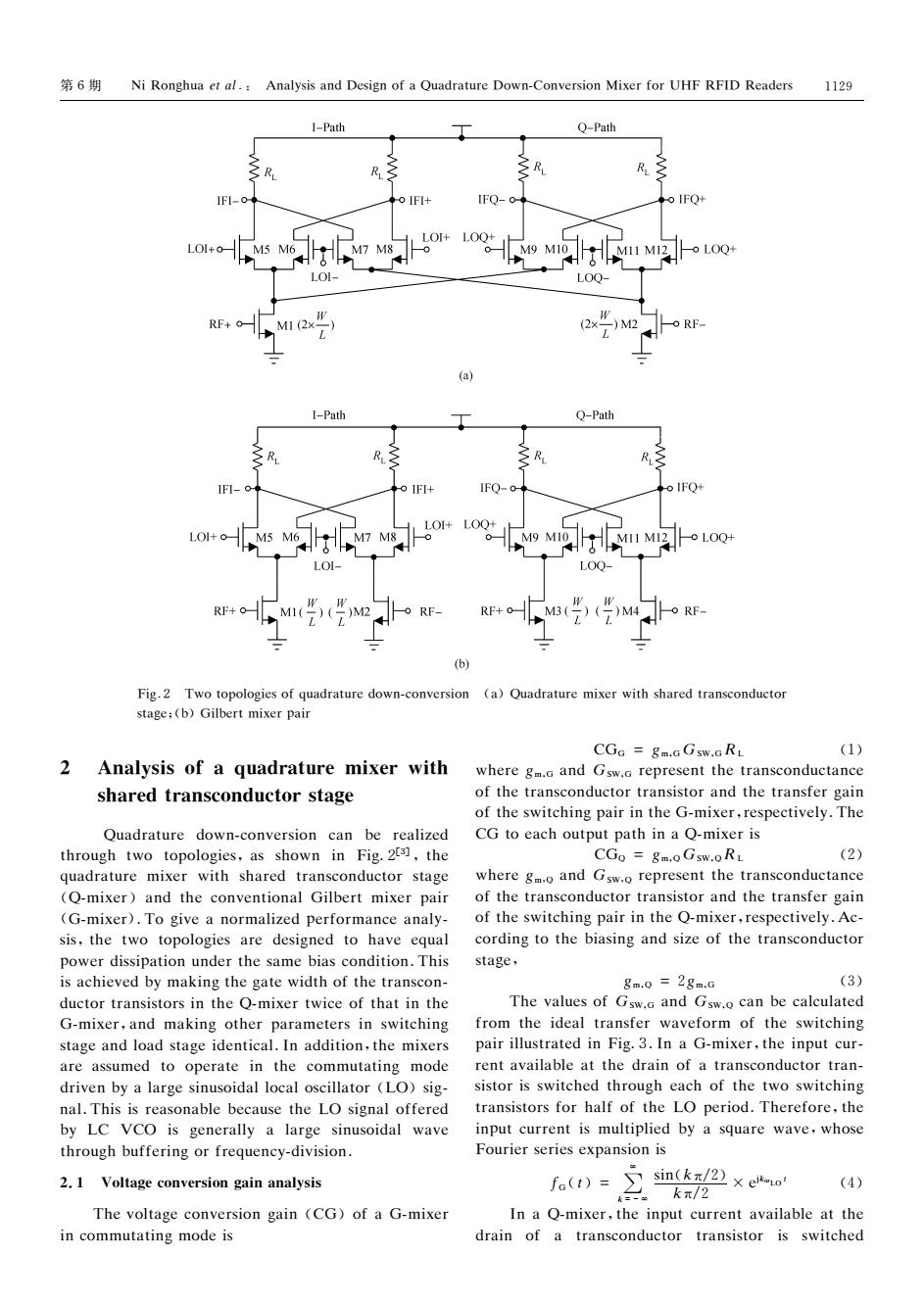
6 Ni Ronghua et al.:Analysis and Design of a Quadrature Down-Conversion Mixer for UHF RFID Readers 1129 1-Path Q-Path IFI- IFQ-o LOQ- RF. M1(2x 2x -)M2 (a) I-Path Q-Path IFI-c IFI+ o IFO MI1 MI2o LOQ+ RF+C M RF (b) Fig.2 Two topologies of quadrature down-conversion (a)Quadrature mixer with shared transconductor stage;(b)Gilbert mixer pair CGa gm.G Gsw.G RL (1) 2 Analysis of a quadrature mixer with where gm.a and Gsw.a represent the transconductance shared transconductor stage of the transconductor transistor and the transfer gain of the switching pair in the G-mixer,respectively.The Quadrature down-conversion can be realized CG to each output path in a Q-mixer is through two topologies,as shown in Fig.2t3],the CGo =gm.oGsw.oRL (2) quadrature mixer with shared transconductor stage where gm.o and Gsw.o represent the transconductance (Q-mixer)and the conventional Gilbert mixer pair of the transconductor transistor and the transfer gain (G-mixer).To give a normalized performance analy-of the switching pair in the Q-mixer,respectively.Ac- sis,the two topologies are designed to have equal cording to the biasing and size of the transconductor power dissipation under the same bias condition.This stage. is achieved by making the gate width of the transcon- gm.0=2gm.0 (3) ductor transistors in the Q-mixer twice of that in the The values of Gsw.a and Gsw.o can be calculated G-mixer,and making other parameters in switching from the ideal transfer waveform of the switching stage and load stage identical.In addition,the mixers pair illustrated in Fig.3.In a G-mixer,the input cur- are assumed to operate in the commutating mode rent available at the drain of a transconductor tran- driven by a large sinusoidal local oscillator (LO)sig- sistor is switched through each of the two switching nal.This is reasonable because the LO signal offered transistors for half of the LO period.Therefore,the by LC VCO is generally a large sinusoidal wave input current is multiplied by a square wave,whose through buffering or frequency-division. Fourier series expansion is 2.1 Voltage conversion gain analysis fa(t)=∑sin(/2×eo 2.kx/2 (4) The voltage conversion gain (CG)of a G-mixer In a Q-mixer,the input current available at the in commutating mode is drain of a transconductor transistor is switched
第6期 犖犻犚狅狀犵犺狌犪犲狋犪犾.: 犃狀犪犾狔狊犻狊犪狀犱犇犲狊犻犵狀狅犳犪犙狌犪犱狉犪狋狌狉犲犇狅狑狀犆狅狀狏犲狉狊犻狅狀犕犻狓犲狉犳狅狉犝犎犉犚犉犐犇 犚犲犪犱犲狉狊 犉犻犵.2 犜狑狅狋狅狆狅犾狅犵犻犲狊狅犳狇狌犪犱狉犪狋狌狉犲犱狅狑狀犮狅狀狏犲狉狊犻狅狀 (犪)犙狌犪犱狉犪狋狌狉犲犿犻狓犲狉狑犻狋犺狊犺犪狉犲犱狋狉犪狀狊犮狅狀犱狌犮狋狅狉 狊狋犪犵犲;(犫)犌犻犾犫犲狉狋犿犻狓犲狉狆犪犻狉 2 犃狀犪犾狔狊犻狊狅犳犪狇狌犪犱狉犪狋狌狉犲犿犻狓犲狉狑犻狋犺 狊犺犪狉犲犱狋狉犪狀狊犮狅狀犱狌犮狋狅狉狊狋犪犵犲 犙狌犪犱狉犪狋狌狉犲 犱狅狑狀犮狅狀狏犲狉狊犻狅狀 犮犪狀 犫犲 狉犲犪犾犻狕犲犱 狋犺狉狅狌犵犺狋狑狅 狋狅狆狅犾狅犵犻犲狊,犪狊狊犺狅狑狀 犻狀 犉犻犵2[3],狋犺犲 狇狌犪犱狉犪狋狌狉犲 犿犻狓犲狉 狑犻狋犺狊犺犪狉犲犱狋狉犪狀狊犮狅狀犱狌犮狋狅狉狊狋犪犵犲 (犙犿犻狓犲狉)犪狀犱狋犺犲犮狅狀狏犲狀狋犻狅狀犪犾犌犻犾犫犲狉狋 犿犻狓犲狉狆犪犻狉 (犌犿犻狓犲狉).犜狅犵犻狏犲犪狀狅狉犿犪犾犻狕犲犱狆犲狉犳狅狉犿犪狀犮犲犪狀犪犾狔 狊犻狊,狋犺犲狋狑狅狋狅狆狅犾狅犵犻犲狊犪狉犲 犱犲狊犻犵狀犲犱狋狅 犺犪狏犲犲狇狌犪犾 狆狅狑犲狉犱犻狊狊犻狆犪狋犻狅狀狌狀犱犲狉狋犺犲狊犪犿犲犫犻犪狊犮狅狀犱犻狋犻狅狀.犜犺犻狊 犻狊犪犮犺犻犲狏犲犱犫狔犿犪犽犻狀犵狋犺犲犵犪狋犲狑犻犱狋犺狅犳狋犺犲狋狉犪狀狊犮狅狀 犱狌犮狋狅狉狋狉犪狀狊犻狊狋狅狉狊犻狀狋犺犲犙犿犻狓犲狉狋狑犻犮犲狅犳狋犺犪狋犻狀狋犺犲 犌犿犻狓犲狉,犪狀犱 犿犪犽犻狀犵狅狋犺犲狉狆犪狉犪犿犲狋犲狉狊犻狀狊狑犻狋犮犺犻狀犵 狊狋犪犵犲犪狀犱犾狅犪犱狊狋犪犵犲犻犱犲狀狋犻犮犪犾.犐狀犪犱犱犻狋犻狅狀,狋犺犲犿犻狓犲狉狊 犪狉犲犪狊狊狌犿犲犱狋狅 狅狆犲狉犪狋犲犻狀 狋犺犲 犮狅犿犿狌狋犪狋犻狀犵 犿狅犱犲 犱狉犻狏犲狀犫狔犪犾犪狉犵犲狊犻狀狌狊狅犻犱犪犾犾狅犮犪犾狅狊犮犻犾犾犪狋狅狉(犔犗)狊犻犵 狀犪犾.犜犺犻狊犻狊狉犲犪狊狅狀犪犫犾犲犫犲犮犪狌狊犲狋犺犲犔犗狊犻犵狀犪犾狅犳犳犲狉犲犱 犫狔 犔犆 犞犆犗 犻狊 犵犲狀犲狉犪犾犾狔 犪犾犪狉犵犲 狊犻狀狌狊狅犻犱犪犾 狑犪狏犲 狋犺狉狅狌犵犺犫狌犳犳犲狉犻狀犵狅狉犳狉犲狇狌犲狀犮狔犱犻狏犻狊犻狅狀. 2.1 犞狅犾狋犪犵犲犮狅狀狏犲狉狊犻狅狀犵犪犻狀犪狀犪犾狔狊犻狊 犜犺犲狏狅犾狋犪犵犲犮狅狀狏犲狉狊犻狅狀犵犪犻狀 (犆犌)狅犳犪犌犿犻狓犲狉 犻狀犮狅犿犿狌狋犪狋犻狀犵犿狅犱犲犻狊 犆犌犌 =犵犿,犌犌犛犠,犌犚犔 (1) 狑犺犲狉犲犵犿,犌 犪狀犱犌犛犠,犌 狉犲狆狉犲狊犲狀狋狋犺犲狋狉犪狀狊犮狅狀犱狌犮狋犪狀犮犲 狅犳狋犺犲狋狉犪狀狊犮狅狀犱狌犮狋狅狉狋狉犪狀狊犻狊狋狅狉犪狀犱狋犺犲狋狉犪狀狊犳犲狉犵犪犻狀 狅犳狋犺犲狊狑犻狋犮犺犻狀犵狆犪犻狉犻狀狋犺犲犌犿犻狓犲狉,狉犲狊狆犲犮狋犻狏犲犾狔.犜犺犲 犆犌狋狅犲犪犮犺狅狌狋狆狌狋狆犪狋犺犻狀犪犙犿犻狓犲狉犻狊 犆犌犙 =犵犿,犙犌犛犠,犙犚犔 (2) 狑犺犲狉犲犵犿,犙 犪狀犱犌犛犠,犙 狉犲狆狉犲狊犲狀狋狋犺犲狋狉犪狀狊犮狅狀犱狌犮狋犪狀犮犲 狅犳狋犺犲狋狉犪狀狊犮狅狀犱狌犮狋狅狉狋狉犪狀狊犻狊狋狅狉犪狀犱狋犺犲狋狉犪狀狊犳犲狉犵犪犻狀 狅犳狋犺犲狊狑犻狋犮犺犻狀犵狆犪犻狉犻狀狋犺犲犙犿犻狓犲狉,狉犲狊狆犲犮狋犻狏犲犾狔.犃犮 犮狅狉犱犻狀犵狋狅狋犺犲犫犻犪狊犻狀犵犪狀犱狊犻狕犲狅犳狋犺犲狋狉犪狀狊犮狅狀犱狌犮狋狅狉 狊狋犪犵犲, 犵犿,犙 =2犵犿,犌 (3) 犜犺犲狏犪犾狌犲狊狅犳犌犛犠,犌 犪狀犱犌犛犠,犙 犮犪狀犫犲犮犪犾犮狌犾犪狋犲犱 犳狉狅犿狋犺犲犻犱犲犪犾狋狉犪狀狊犳犲狉 狑犪狏犲犳狅狉犿 狅犳狋犺犲狊狑犻狋犮犺犻狀犵 狆犪犻狉犻犾犾狌狊狋狉犪狋犲犱犻狀犉犻犵3.犐狀犪犌犿犻狓犲狉,狋犺犲犻狀狆狌狋犮狌狉 狉犲狀狋犪狏犪犻犾犪犫犾犲犪狋狋犺犲犱狉犪犻狀狅犳犪狋狉犪狀狊犮狅狀犱狌犮狋狅狉狋狉犪狀 狊犻狊狋狅狉犻狊狊狑犻狋犮犺犲犱狋犺狉狅狌犵犺犲犪犮犺狅犳狋犺犲狋狑狅狊狑犻狋犮犺犻狀犵 狋狉犪狀狊犻狊狋狅狉狊犳狅狉犺犪犾犳狅犳狋犺犲犔犗 狆犲狉犻狅犱.犜犺犲狉犲犳狅狉犲,狋犺犲 犻狀狆狌狋犮狌狉狉犲狀狋犻狊犿狌犾狋犻狆犾犻犲犱犫狔犪狊狇狌犪狉犲 狑犪狏犲,狑犺狅狊犲 犉狅狌狉犻犲狉狊犲狉犻犲狊犲狓狆犪狀狊犻狅狀犻狊 犳犌(狋)= ∑ ∞ 犽=-∞ 狊犻狀(犽π/2) 犽π/2 ×犲犼犽ω犔犗狋 (4) 犐狀犪犙犿犻狓犲狉,狋犺犲犻狀狆狌狋犮狌狉狉犲狀狋犪狏犪犻犾犪犫犾犲犪狋狋犺犲 犱狉犪犻狀 狅犳 犪 狋狉犪狀狊犮狅狀犱狌犮狋狅狉 狋狉犪狀狊犻狊狋狅狉 犻狊 狊狑犻狋犮犺犲犱 1129
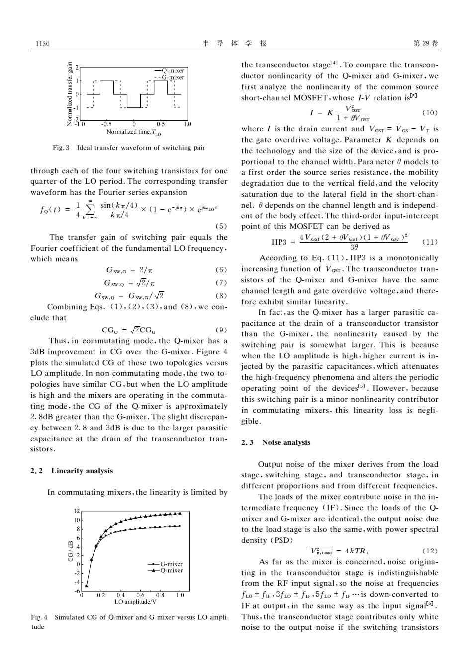
1130 半导体学报 第29卷 the transconductor staget.To compare the transcon- -Q-mixer -G-mixer ductor nonlinearity of the Q-mixer and G-mixer,we first analyze the nonlinearity of the common source short-channel MOSFET,whose I-V relation ists] 1=水深 (10) -1.0 -0.5 0 0.5 Normalized time.TLo where I is the drain current and Vasr=Vas-Vr is the gate overdrive voltage.Parameter K depends on Fig.3 Ideal transfer waveform of switching pair the technology and the size of the device,and is pro- portional to the channel width.Parameter 0 models to through each of the four switching transistors for one a first order the source series resistance,the mobility quarter of the LO period.The corresponding transfer degradation due to the vertical field,and the velocity waveform has the Fourier series expansion saturation due to the lateral field in the short-chan- fo(t)= 1 4 sin(k元/4×(1-ekr)×euo nel.0 depends on the channel length and is independ- kπ/4 ent of the body effect.The third-order input-intercept (5) point of this MOSFET can be derived as The transfer gain of switching pair equals the IIP3 =4Vcsr(2 +avasr)(1+VT) (11) Fourier coefficient of the fundamental LO frequency, 30 which means According to Eq.(11),IIP3 is a monotonically Gsw.6=2/π (6) increasing function of Vosr.The transconductor tran- Gsw.0=√2/π (7) sistors of the Q-mixer and G-mixer have the same Gsw.0 Gsw.G/V2 (8) channel length and gate overdrive voltage,and there- Combining Eqs.(1),(2),(3),and (8),we con- fore exhibit similar linearity. In fact,as the Q-mixer has a larger parasitic ca- clude that pacitance at the drain of a transconductor transistor CGo=√ECGa (9) than the G-mixer,the nonlinearity caused by the Thus,in commutating mode,the Q-mixer has a switching pair is somewhat larger.This is because 3dB improvement in CG over the G-mixer.Figure 4 when the LO amplitude is high,higher current is in- plots the simulated CG of these two topologies versus jected by the parasitic capacitances,which attenuates LO amplitude.In non-commutating mode,the two to- the high-frequency phenomena and alters the periodic pologies have similar CG,but when the LO amplitude operating point of the devicests].However,because is high and the mixers are operating in the commuta- this switching pair is a minor nonlinearity contributor ting mode,the CG of the Q-mixer is approximately in commutating mixers,this linearity loss is negli- 2.8dB greater than the G-mixer.The slight discrepan- gible cy between 2.8 and 3dB is due to the larger parasitic capacitance at the drain of the transconductor tran- 2.3 Noise analysis sistors. Output noise of the mixer derives from the load 2.2 Linearity analysis stage,switching stage,and transconductor stage,in different proportions and from different frequencies. In commutating mixers,the linearity is limited by The loads of the mixer contribute noise in the in- termediate frequency (IF).Since the loads of the Q- 10 mixer and G-mixer are identical,the output noise due 8 to the load stage is also the same,with power spectral 6 density (PSD) 4 Vi.Lod 4kTRL (12) 2 0 -G-mixer As far as the mixer is concerned,noise origina- Q-mixer ting in the transconductor stage is indistinguishable from the RF input signal,so the noise at frequencies 0.2 0.40.6 0.8 1.0 fo±fir,3fio±fr,5fio±fr…is down-converted to LO amplitude/V IF at output,in the same way as the input signalte. Fig.4 Simulated CG of Q-mixer and G-mixer versus LO ampli- Thus,the transconductor stage contributes only white tude noise to the output noise if the switching transistors
半 导 体 学 报 第29卷 犉犻犵.3 犐犱犲犪犾狋狉犪狀狊犳犲狉狑犪狏犲犳狅狉犿狅犳狊狑犻狋犮犺犻狀犵狆犪犻狉 狋犺狉狅狌犵犺犲犪犮犺狅犳狋犺犲犳狅狌狉狊狑犻狋犮犺犻狀犵狋狉犪狀狊犻狊狋狅狉狊犳狅狉狅狀犲 狇狌犪狉狋犲狉狅犳狋犺犲犔犗狆犲狉犻狅犱.犜犺犲犮狅狉狉犲狊狆狅狀犱犻狀犵狋狉犪狀狊犳犲狉 狑犪狏犲犳狅狉犿犺犪狊狋犺犲犉狅狌狉犻犲狉狊犲狉犻犲狊犲狓狆犪狀狊犻狅狀 犳犙(狋)= 1 4 ∑ ∞ 犽=-∞ 狊犻狀(犽π/4) 犽π/4 × (1-犲-犼犽π)×犲犼犽ω犔犗狋 (5) 犜犺犲狋狉犪狀狊犳犲狉犵犪犻狀狅犳狊狑犻狋犮犺犻狀犵狆犪犻狉犲狇狌犪犾狊狋犺犲 犉狅狌狉犻犲狉犮狅犲犳犳犻犮犻犲狀狋狅犳狋犺犲犳狌狀犱犪犿犲狀狋犪犾犔犗犳狉犲狇狌犲狀犮狔, 狑犺犻犮犺犿犲犪狀狊 犌犛犠,犌 =2/π (6) 犌犛犠,犙 = 槡2/π (7) 犌犛犠,犙 = 犌犛犠,犌/槡2 (8) 犆狅犿犫犻狀犻狀犵犈狇狊.(1),(2),(3),犪狀犱 (8),狑犲犮狅狀 犮犾狌犱犲狋犺犪狋 犆犌犙 = 槡2犆犌犌 (9) 犜犺狌狊,犻狀犮狅犿犿狌狋犪狋犻狀犵 犿狅犱犲,狋犺犲 犙犿犻狓犲狉犺犪狊犪 3犱犅犻犿狆狉狅狏犲犿犲狀狋犻狀犆犌 狅狏犲狉狋犺犲犌犿犻狓犲狉.犉犻犵狌狉犲4 狆犾狅狋狊狋犺犲狊犻犿狌犾犪狋犲犱犆犌狅犳狋犺犲狊犲狋狑狅狋狅狆狅犾狅犵犻犲狊狏犲狉狊狌狊 犔犗犪犿狆犾犻狋狌犱犲.犐狀狀狅狀犮狅犿犿狌狋犪狋犻狀犵犿狅犱犲,狋犺犲狋狑狅狋狅 狆狅犾狅犵犻犲狊犺犪狏犲狊犻犿犻犾犪狉犆犌,犫狌狋狑犺犲狀狋犺犲犔犗犪犿狆犾犻狋狌犱犲 犻狊犺犻犵犺犪狀犱狋犺犲犿犻狓犲狉狊犪狉犲狅狆犲狉犪狋犻狀犵犻狀狋犺犲犮狅犿犿狌狋犪 狋犻狀犵犿狅犱犲,狋犺犲犆犌 狅犳狋犺犲 犙犿犻狓犲狉犻狊犪狆狆狉狅狓犻犿犪狋犲犾狔 28犱犅犵狉犲犪狋犲狉狋犺犪狀狋犺犲犌犿犻狓犲狉.犜犺犲狊犾犻犵犺狋犱犻狊犮狉犲狆犪狀 犮狔犫犲狋狑犲犲狀28犪狀犱3犱犅犻狊犱狌犲狋狅狋犺犲犾犪狉犵犲狉狆犪狉犪狊犻狋犻犮 犮犪狆犪犮犻狋犪狀犮犲犪狋狋犺犲犱狉犪犻狀狅犳狋犺犲狋狉犪狀狊犮狅狀犱狌犮狋狅狉狋狉犪狀 狊犻狊狋狅狉狊. 2.2 犔犻狀犲犪狉犻狋狔犪狀犪犾狔狊犻狊 犐狀犮狅犿犿狌狋犪狋犻狀犵犿犻狓犲狉狊,狋犺犲犾犻狀犲犪狉犻狋狔犻狊犾犻犿犻狋犲犱犫狔 犉犻犵.4 犛犻犿狌犾犪狋犲犱犆犌狅犳犙犿犻狓犲狉犪狀犱犌犿犻狓犲狉狏犲狉狊狌狊犔犗犪犿狆犾犻 狋狌犱犲 狋犺犲狋狉犪狀狊犮狅狀犱狌犮狋狅狉狊狋犪犵犲[4] .犜狅犮狅犿狆犪狉犲狋犺犲狋狉犪狀狊犮狅狀 犱狌犮狋狅狉狀狅狀犾犻狀犲犪狉犻狋狔狅犳狋犺犲犙犿犻狓犲狉犪狀犱 犌犿犻狓犲狉,狑犲 犳犻狉狊狋犪狀犪犾狔狕犲狋犺犲狀狅狀犾犻狀犲犪狉犻狋狔狅犳狋犺犲犮狅犿犿狅狀狊狅狌狉犮犲 狊犺狅狉狋犮犺犪狀狀犲犾犕犗犛犉犈犜,狑犺狅狊犲犐犞狉犲犾犪狋犻狅狀犻狊[5] 犐 = 犓 犞2 犌犛犜 1+θ犞犌犛犜 (10) 狑犺犲狉犲犐犻狊狋犺犲犱狉犪犻狀犮狌狉狉犲狀狋犪狀犱犞犌犛犜 =犞犌犛 -犞犜犻狊 狋犺犲犵犪狋犲狅狏犲狉犱狉犻狏犲狏狅犾狋犪犵犲.犘犪狉犪犿犲狋犲狉犓 犱犲狆犲狀犱狊狅狀 狋犺犲狋犲犮犺狀狅犾狅犵狔犪狀犱狋犺犲狊犻狕犲狅犳狋犺犲犱犲狏犻犮犲,犪狀犱犻狊狆狉狅 狆狅狉狋犻狅狀犪犾狋狅狋犺犲犮犺犪狀狀犲犾狑犻犱狋犺.犘犪狉犪犿犲狋犲狉θ犿狅犱犲犾狊狋狅 犪犳犻狉狊狋狅狉犱犲狉狋犺犲狊狅狌狉犮犲狊犲狉犻犲狊狉犲狊犻狊狋犪狀犮犲,狋犺犲犿狅犫犻犾犻狋狔 犱犲犵狉犪犱犪狋犻狅狀犱狌犲狋狅狋犺犲狏犲狉狋犻犮犪犾犳犻犲犾犱,犪狀犱狋犺犲狏犲犾狅犮犻狋狔 狊犪狋狌狉犪狋犻狅狀犱狌犲狋狅狋犺犲犾犪狋犲狉犪犾犳犻犲犾犱犻狀狋犺犲狊犺狅狉狋犮犺犪狀 狀犲犾.θ犱犲狆犲狀犱狊狅狀狋犺犲犮犺犪狀狀犲犾犾犲狀犵狋犺犪狀犱犻狊犻狀犱犲狆犲狀犱 犲狀狋狅犳狋犺犲犫狅犱狔犲犳犳犲犮狋.犜犺犲狋犺犻狉犱狅狉犱犲狉犻狀狆狌狋犻狀狋犲狉犮犲狆狋 狆狅犻狀狋狅犳狋犺犻狊犕犗犛犉犈犜犮犪狀犫犲犱犲狉犻狏犲犱犪狊 犐犐犘3=4犞犌犛犜(2+θ犞犌犛犜)(1+θ犞犌犛犜)2 3θ (11) 犃犮犮狅狉犱犻狀犵狋狅犈狇.(11),犐犐犘3犻狊犪 犿狅狀狅狋狅狀犻犮犪犾犾狔 犻狀犮狉犲犪狊犻狀犵犳狌狀犮狋犻狅狀狅犳犞犌犛犜.犜犺犲狋狉犪狀狊犮狅狀犱狌犮狋狅狉狋狉犪狀 狊犻狊狋狅狉狊狅犳狋犺犲 犙犿犻狓犲狉犪狀犱 犌犿犻狓犲狉犺犪狏犲狋犺犲狊犪犿犲 犮犺犪狀狀犲犾犾犲狀犵狋犺犪狀犱犵犪狋犲狅狏犲狉犱狉犻狏犲狏狅犾狋犪犵犲,犪狀犱狋犺犲狉犲 犳狅狉犲犲狓犺犻犫犻狋狊犻犿犻犾犪狉犾犻狀犲犪狉犻狋狔. 犐狀犳犪犮狋,犪狊狋犺犲犙犿犻狓犲狉犺犪狊犪犾犪狉犵犲狉狆犪狉犪狊犻狋犻犮犮犪 狆犪犮犻狋犪狀犮犲犪狋狋犺犲犱狉犪犻狀狅犳犪狋狉犪狀狊犮狅狀犱狌犮狋狅狉狋狉犪狀狊犻狊狋狅狉 狋犺犪狀狋犺犲 犌犿犻狓犲狉,狋犺犲 狀狅狀犾犻狀犲犪狉犻狋狔 犮犪狌狊犲犱 犫狔 狋犺犲 狊狑犻狋犮犺犻狀犵狆犪犻狉犻狊狊狅犿犲狑犺犪狋犾犪狉犵犲狉.犜犺犻狊犻狊犫犲犮犪狌狊犲 狑犺犲狀狋犺犲犔犗犪犿狆犾犻狋狌犱犲犻狊犺犻犵犺,犺犻犵犺犲狉犮狌狉狉犲狀狋犻狊犻狀 犼犲犮狋犲犱犫狔狋犺犲狆犪狉犪狊犻狋犻犮犮犪狆犪犮犻狋犪狀犮犲狊,狑犺犻犮犺犪狋狋犲狀狌犪狋犲狊 狋犺犲犺犻犵犺犳狉犲狇狌犲狀犮狔狆犺犲狀狅犿犲狀犪犪狀犱犪犾狋犲狉狊狋犺犲狆犲狉犻狅犱犻犮 狅狆犲狉犪狋犻狀犵狆狅犻狀狋狅犳狋犺犲犱犲狏犻犮犲狊[5] .犎狅狑犲狏犲狉,犫犲犮犪狌狊犲 狋犺犻狊狊狑犻狋犮犺犻狀犵狆犪犻狉犻狊犪犿犻狀狅狉狀狅狀犾犻狀犲犪狉犻狋狔犮狅狀狋狉犻犫狌狋狅狉 犻狀犮狅犿犿狌狋犪狋犻狀犵 犿犻狓犲狉狊,狋犺犻狊犾犻狀犲犪狉犻狋狔犾狅狊狊犻狊狀犲犵犾犻 犵犻犫犾犲. 2.3 犖狅犻狊犲犪狀犪犾狔狊犻狊 犗狌狋狆狌狋狀狅犻狊犲狅犳狋犺犲犿犻狓犲狉犱犲狉犻狏犲狊犳狉狅犿狋犺犲犾狅犪犱 狊狋犪犵犲,狊狑犻狋犮犺犻狀犵狊狋犪犵犲,犪狀犱狋狉犪狀狊犮狅狀犱狌犮狋狅狉狊狋犪犵犲,犻狀 犱犻犳犳犲狉犲狀狋狆狉狅狆狅狉狋犻狅狀狊犪狀犱犳狉狅犿犱犻犳犳犲狉犲狀狋犳狉犲狇狌犲狀犮犻犲狊. 犜犺犲犾狅犪犱狊狅犳狋犺犲犿犻狓犲狉犮狅狀狋狉犻犫狌狋犲狀狅犻狊犲犻狀狋犺犲犻狀 狋犲狉犿犲犱犻犪狋犲犳狉犲狇狌犲狀犮狔 (犐犉).犛犻狀犮犲狋犺犲犾狅犪犱狊狅犳狋犺犲犙 犿犻狓犲狉犪狀犱犌犿犻狓犲狉犪狉犲犻犱犲狀狋犻犮犪犾,狋犺犲狅狌狋狆狌狋狀狅犻狊犲犱狌犲 狋狅狋犺犲犾狅犪犱狊狋犪犵犲犻狊犪犾狊狅狋犺犲狊犪犿犲,狑犻狋犺狆狅狑犲狉狊狆犲犮狋狉犪犾 犱犲狀狊犻狋狔(犘犛犇) 犞2 狀,犔狅犪犱 =4犽犜犚犔 (12) 犃狊犳犪狉犪狊狋犺犲犿犻狓犲狉犻狊犮狅狀犮犲狉狀犲犱,狀狅犻狊犲狅狉犻犵犻狀犪 狋犻狀犵犻狀狋犺犲狋狉犪狀狊犮狅狀犱狌犮狋狅狉狊狋犪犵犲犻狊犻狀犱犻狊狋犻狀犵狌犻狊犺犪犫犾犲 犳狉狅犿狋犺犲犚犉犻狀狆狌狋狊犻犵狀犪犾,狊狅狋犺犲狀狅犻狊犲犪狋犳狉犲狇狌犲狀犮犻犲狊 犳犔犗±犳犐犉,3犳犔犗 ±犳犐犉,5犳犔犗 ±犳犐犉 …犻狊犱狅狑狀犮狅狀狏犲狉狋犲犱狋狅 犐犉犪狋狅狌狋狆狌狋,犻狀狋犺犲狊犪犿犲狑犪狔犪狊狋犺犲犻狀狆狌狋狊犻犵狀犪犾[6] . 犜犺狌狊,狋犺犲狋狉犪狀狊犮狅狀犱狌犮狋狅狉狊狋犪犵犲犮狅狀狋狉犻犫狌狋犲狊狅狀犾狔狑犺犻狋犲 狀狅犻狊犲狋狅狋犺犲狅狌狋狆狌狋狀狅犻狊犲犻犳狋犺犲狊狑犻狋犮犺犻狀犵狋狉犪狀狊犻狊狋狅狉狊 1130
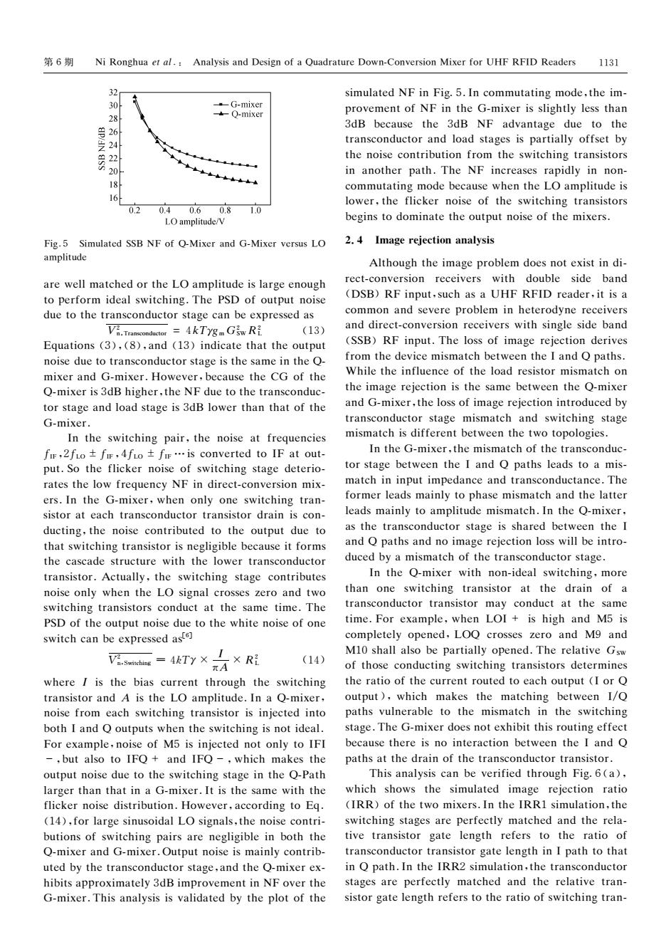
第6期 Ni Ronghua et al.Analysis and Design of a Quadrature Down-Conversion Mixer for UHF RFID Readers 1131 32 simulated NF in Fig.5.In commutating mode,the im- 30 -G-mixer -Q-mixer provement of NF in the G-mixer is slightly less than 号2 3dB because the 3dB NF advantage due to the 4 transconductor and load stages is partially offset by the noise contribution from the switching transistors in another path.The NF increases rapidly in non- 18 commutating mode because when the LO amplitude is 16 lower,the flicker noise of the switching transistors 0.2 0.40.60.8 1.0 LO amplitude/V begins to dominate the output noise of the mixers. Fig.5 Simulated SSB NF of Q-Mixer and G-Mixer versus LO 2.4 Image rejection analysis amplitude Although the image problem does not exist in di- are well matched or the LO amplitude is large enough rect-conversion receivers with double side band to perform ideal switching.The PSD of output noise (DSB)RF input,such as a UHF RFID reader,it is a due to the transconductor stage can be expressed as common and severe problem in heterodyne receivers Va.Transconductor =4kTygm GSw Ri (13) and direct-conversion receivers with single side band Equations (3),(8),and(13)indicate that the output (SSB)RF input.The loss of image rejection derives noise due to transconductor stage is the same in the Q- from the device mismatch between the I and Q paths. mixer and G-mixer.However,because the CG of the While the influence of the load resistor mismatch on Q-mixer is 3dB higher,the NF due to the transconduc- the image rejection is the same between the Q-mixer tor stage and load stage is 3dB lower than that of the and G-mixer,the loss of image rejection introduced by G-mixer. transconductor stage mismatch and switching stage In the switching pair,the noise at frequencies mismatch is different between the two topologies. fr,2fio±fw,4fo±fr…is converted to IF at out- In the G-mixer,the mismatch of the transconduc- put.So the flicker noise of switching stage deterio- tor stage between the I and Q paths leads to a mis- rates the low frequency NF in direct-conversion mix- match in input impedance and transconductance.The ers.In the G-mixer,when only one switching tran- former leads mainly to phase mismatch and the latter sistor at each transconductor transistor drain is con- leads mainly to amplitude mismatch.In the Q-mixer, ducting,the noise contributed to the output due to as the transconductor stage is shared between the I that switching transistor is negligible because it forms and Q paths and no image rejection loss will be intro- the cascade structure with the lower transconductor duced by a mismatch of the transconductor stage. transistor.Actually,the switching stage contributes In the Q-mixer with non-ideal switching,more noise only when the LO signal crosses zero and two than one switching transistor at the drain of a switching transistors conduct at the same time.The transconductor transistor may conduct at the same PSD of the output noise due to the white noise of one time.For example,when LOI is high and M5 is switch can be expressed aste] completely opened,LOQ crosses zero and M9 and Viesmebine =4T7xR M10 shall also be partially opened.The relative Gsw (14) πA of those conducting switching transistors determines where I is the bias current through the switching the ratio of the current routed to each output (I or Q transistor and A is the LO amplitude.In a Q-mixer, output),which makes the matching between I/Q noise from each switching transistor is injected into paths vulnerable to the mismatch in the switching both I and Q outputs when the switching is not ideal. stage.The G-mixer does not exhibit this routing effect For example,noise of M5 is injected not only to IFI because there is no interaction between the I and Q -but also to IFO+and IFO-,which makes the paths at the drain of the transconductor transistor. output noise due to the switching stage in the Q-Path This analysis can be verified through Fig.6(a), larger than that in a G-mixer.It is the same with the which shows the simulated image rejection ratio flicker noise distribution.However,according to Eq. (IRR)of the two mixers.In the IRRI simulation,the (14),for large sinusoidal LO signals,the noise contri- switching stages are perfectly matched and the rela- butions of switching pairs are negligible in both the tive transistor gate length refers to the ratio of O-mixer and G-mixer.Output noise is mainly contrib-transconductor transistor gate length in I path to that uted by the transconductor stage,and the Q-mixer ex-in Q path.In the IRR2 simulation,the transconductor hibits approximately 3dB improvement in NF over the stages are perfectly matched and the relative tran- G-mixer.This analysis is validated by the plot of the sistor gate length refers to the ratio of switching tran-
第6期 犖犻犚狅狀犵犺狌犪犲狋犪犾.: 犃狀犪犾狔狊犻狊犪狀犱犇犲狊犻犵狀狅犳犪犙狌犪犱狉犪狋狌狉犲犇狅狑狀犆狅狀狏犲狉狊犻狅狀犕犻狓犲狉犳狅狉犝犎犉犚犉犐犇 犚犲犪犱犲狉狊 犉犻犵.5 犛犻犿狌犾犪狋犲犱犛犛犅 犖犉狅犳犙犕犻狓犲狉犪狀犱犌犕犻狓犲狉狏犲狉狊狌狊犔犗 犪犿狆犾犻狋狌犱犲 犪狉犲狑犲犾犾犿犪狋犮犺犲犱狅狉狋犺犲犔犗犪犿狆犾犻狋狌犱犲犻狊犾犪狉犵犲犲狀狅狌犵犺 狋狅狆犲狉犳狅狉犿犻犱犲犪犾狊狑犻狋犮犺犻狀犵.犜犺犲犘犛犇狅犳狅狌狋狆狌狋狀狅犻狊犲 犱狌犲狋狅狋犺犲狋狉犪狀狊犮狅狀犱狌犮狋狅狉狊狋犪犵犲犮犪狀犫犲犲狓狆狉犲狊狊犲犱犪狊 犞2 狀,犜狉犪狀狊犮狅狀犱狌犮狋狅狉 =4犽犜γ犵犿犌2 犛犠犚2 犔 (13) 犈狇狌犪狋犻狅狀狊(3),(8),犪狀犱 (13)犻狀犱犻犮犪狋犲狋犺犪狋狋犺犲狅狌狋狆狌狋 狀狅犻狊犲犱狌犲狋狅狋狉犪狀狊犮狅狀犱狌犮狋狅狉狊狋犪犵犲犻狊狋犺犲狊犪犿犲犻狀狋犺犲犙 犿犻狓犲狉犪狀犱犌犿犻狓犲狉.犎狅狑犲狏犲狉,犫犲犮犪狌狊犲狋犺犲犆犌狅犳狋犺犲 犙犿犻狓犲狉犻狊3犱犅犺犻犵犺犲狉,狋犺犲犖犉犱狌犲狋狅狋犺犲狋狉犪狀狊犮狅狀犱狌犮 狋狅狉狊狋犪犵犲犪狀犱犾狅犪犱狊狋犪犵犲犻狊3犱犅犾狅狑犲狉狋犺犪狀狋犺犪狋狅犳狋犺犲 犌犿犻狓犲狉. 犐狀狋犺犲狊狑犻狋犮犺犻狀犵 狆犪犻狉,狋犺犲 狀狅犻狊犲犪狋犳狉犲狇狌犲狀犮犻犲狊 犳犐犉,2犳犔犗 ±犳犐犉,4犳犔犗 ±犳犐犉 …犻狊犮狅狀狏犲狉狋犲犱狋狅犐犉犪狋狅狌狋 狆狌狋.犛狅狋犺犲犳犾犻犮犽犲狉狀狅犻狊犲狅犳狊狑犻狋犮犺犻狀犵狊狋犪犵犲犱犲狋犲狉犻狅 狉犪狋犲狊狋犺犲犾狅狑犳狉犲狇狌犲狀犮狔犖犉犻狀犱犻狉犲犮狋犮狅狀狏犲狉狊犻狅狀犿犻狓 犲狉狊.犐狀狋犺犲 犌犿犻狓犲狉,狑犺犲狀狅狀犾狔狅狀犲狊狑犻狋犮犺犻狀犵狋狉犪狀 狊犻狊狋狅狉犪狋犲犪犮犺狋狉犪狀狊犮狅狀犱狌犮狋狅狉狋狉犪狀狊犻狊狋狅狉犱狉犪犻狀犻狊犮狅狀 犱狌犮狋犻狀犵,狋犺犲狀狅犻狊犲犮狅狀狋狉犻犫狌狋犲犱狋狅狋犺犲狅狌狋狆狌狋犱狌犲狋狅 狋犺犪狋狊狑犻狋犮犺犻狀犵狋狉犪狀狊犻狊狋狅狉犻狊狀犲犵犾犻犵犻犫犾犲犫犲犮犪狌狊犲犻狋犳狅狉犿狊 狋犺犲犮犪狊犮犪犱犲狊狋狉狌犮狋狌狉犲 狑犻狋犺狋犺犲犾狅狑犲狉狋狉犪狀狊犮狅狀犱狌犮狋狅狉 狋狉犪狀狊犻狊狋狅狉.犃犮狋狌犪犾犾狔,狋犺犲狊狑犻狋犮犺犻狀犵狊狋犪犵犲犮狅狀狋狉犻犫狌狋犲狊 狀狅犻狊犲狅狀犾狔狑犺犲狀狋犺犲犔犗狊犻犵狀犪犾犮狉狅狊狊犲狊狕犲狉狅犪狀犱狋狑狅 狊狑犻狋犮犺犻狀犵狋狉犪狀狊犻狊狋狅狉狊犮狅狀犱狌犮狋犪狋狋犺犲狊犪犿犲狋犻犿犲.犜犺犲 犘犛犇狅犳狋犺犲狅狌狋狆狌狋狀狅犻狊犲犱狌犲狋狅狋犺犲狑犺犻狋犲狀狅犻狊犲狅犳狅狀犲 狊狑犻狋犮犺犮犪狀犫犲犲狓狆狉犲狊狊犲犱犪狊[6] 犞2 n,Switching =4犽犜γ× 犐 π犃×犚2 犔 (14) 狑犺犲狉犲犐 犻狊狋犺犲 犫犻犪狊犮狌狉狉犲狀狋狋犺狉狅狌犵犺狋犺犲狊狑犻狋犮犺犻狀犵 狋狉犪狀狊犻狊狋狅狉犪狀犱犃犻狊狋犺犲犔犗犪犿狆犾犻狋狌犱犲.犐狀犪犙犿犻狓犲狉, 狀狅犻狊犲犳狉狅犿 犲犪犮犺狊狑犻狋犮犺犻狀犵狋狉犪狀狊犻狊狋狅狉犻狊犻狀犼犲犮狋犲犱犻狀狋狅 犫狅狋犺犐犪狀犱犙狅狌狋狆狌狋狊狑犺犲狀狋犺犲狊狑犻狋犮犺犻狀犵犻狊狀狅狋犻犱犲犪犾. 犉狅狉犲狓犪犿狆犾犲,狀狅犻狊犲狅犳犕5犻狊犻狀犼犲犮狋犲犱狀狅狋狅狀犾狔狋狅犐犉犐 -,犫狌狋犪犾狊狅狋狅犐犉犙+ 犪狀犱犐犉犙-,狑犺犻犮犺 犿犪犽犲狊狋犺犲 狅狌狋狆狌狋狀狅犻狊犲犱狌犲狋狅狋犺犲狊狑犻狋犮犺犻狀犵狊狋犪犵犲犻狀狋犺犲犙犘犪狋犺 犾犪狉犵犲狉狋犺犪狀狋犺犪狋犻狀犪犌犿犻狓犲狉.犐狋犻狊狋犺犲狊犪犿犲狑犻狋犺狋犺犲 犳犾犻犮犽犲狉狀狅犻狊犲犱犻狊狋狉犻犫狌狋犻狅狀.犎狅狑犲狏犲狉,犪犮犮狅狉犱犻狀犵狋狅犈狇. (14),犳狅狉犾犪狉犵犲狊犻狀狌狊狅犻犱犪犾犔犗狊犻犵狀犪犾狊,狋犺犲狀狅犻狊犲犮狅狀狋狉犻 犫狌狋犻狅狀狊狅犳狊狑犻狋犮犺犻狀犵狆犪犻狉狊犪狉犲狀犲犵犾犻犵犻犫犾犲犻狀犫狅狋犺狋犺犲 犙犿犻狓犲狉犪狀犱犌犿犻狓犲狉.犗狌狋狆狌狋狀狅犻狊犲犻狊犿犪犻狀犾狔犮狅狀狋狉犻犫 狌狋犲犱犫狔狋犺犲狋狉犪狀狊犮狅狀犱狌犮狋狅狉狊狋犪犵犲,犪狀犱狋犺犲犙犿犻狓犲狉犲狓 犺犻犫犻狋狊犪狆狆狉狅狓犻犿犪狋犲犾狔3犱犅犻犿狆狉狅狏犲犿犲狀狋犻狀犖犉狅狏犲狉狋犺犲 犌犿犻狓犲狉.犜犺犻狊犪狀犪犾狔狊犻狊犻狊狏犪犾犻犱犪狋犲犱犫狔狋犺犲狆犾狅狋狅犳狋犺犲 狊犻犿狌犾犪狋犲犱犖犉犻狀犉犻犵5.犐狀犮狅犿犿狌狋犪狋犻狀犵犿狅犱犲,狋犺犲犻犿 狆狉狅狏犲犿犲狀狋狅犳犖犉犻狀狋犺犲犌犿犻狓犲狉犻狊狊犾犻犵犺狋犾狔犾犲狊狊狋犺犪狀 3犱犅 犫犲犮犪狌狊犲 狋犺犲 3犱犅 犖犉 犪犱狏犪狀狋犪犵犲 犱狌犲 狋狅 狋犺犲 狋狉犪狀狊犮狅狀犱狌犮狋狅狉犪狀犱犾狅犪犱狊狋犪犵犲狊犻狊狆犪狉狋犻犪犾犾狔狅犳犳狊犲狋犫狔 狋犺犲狀狅犻狊犲犮狅狀狋狉犻犫狌狋犻狅狀犳狉狅犿狋犺犲狊狑犻狋犮犺犻狀犵狋狉犪狀狊犻狊狋狅狉狊 犻狀犪狀狅狋犺犲狉狆犪狋犺.犜犺犲 犖犉犻狀犮狉犲犪狊犲狊狉犪狆犻犱犾狔犻狀 狀狅狀 犮狅犿犿狌狋犪狋犻狀犵犿狅犱犲犫犲犮犪狌狊犲狑犺犲狀狋犺犲犔犗犪犿狆犾犻狋狌犱犲犻狊 犾狅狑犲狉,狋犺犲犳犾犻犮犽犲狉狀狅犻狊犲狅犳狋犺犲狊狑犻狋犮犺犻狀犵狋狉犪狀狊犻狊狋狅狉狊 犫犲犵犻狀狊狋狅犱狅犿犻狀犪狋犲狋犺犲狅狌狋狆狌狋狀狅犻狊犲狅犳狋犺犲犿犻狓犲狉狊. 2.4 犐犿犪犵犲狉犲犼犲犮狋犻狅狀犪狀犪犾狔狊犻狊 犃犾狋犺狅狌犵犺狋犺犲犻犿犪犵犲狆狉狅犫犾犲犿犱狅犲狊狀狅狋犲狓犻狊狋犻狀犱犻 狉犲犮狋犮狅狀狏犲狉狊犻狅狀 狉犲犮犲犻狏犲狉狊 狑犻狋犺 犱狅狌犫犾犲 狊犻犱犲 犫犪狀犱 (犇犛犅)犚犉犻狀狆狌狋,狊狌犮犺犪狊犪犝犎犉 犚犉犐犇狉犲犪犱犲狉,犻狋犻狊犪 犮狅犿犿狅狀犪狀犱狊犲狏犲狉犲狆狉狅犫犾犲犿犻狀犺犲狋犲狉狅犱狔狀犲狉犲犮犲犻狏犲狉狊 犪狀犱犱犻狉犲犮狋犮狅狀狏犲狉狊犻狅狀狉犲犮犲犻狏犲狉狊狑犻狋犺狊犻狀犵犾犲狊犻犱犲犫犪狀犱 (犛犛犅)犚犉犻狀狆狌狋.犜犺犲犾狅狊狊狅犳犻犿犪犵犲狉犲犼犲犮狋犻狅狀犱犲狉犻狏犲狊 犳狉狅犿狋犺犲犱犲狏犻犮犲犿犻狊犿犪狋犮犺犫犲狋狑犲犲狀狋犺犲犐犪狀犱犙狆犪狋犺狊. 犠犺犻犾犲狋犺犲犻狀犳犾狌犲狀犮犲狅犳狋犺犲犾狅犪犱狉犲狊犻狊狋狅狉犿犻狊犿犪狋犮犺狅狀 狋犺犲犻犿犪犵犲狉犲犼犲犮狋犻狅狀犻狊狋犺犲狊犪犿犲犫犲狋狑犲犲狀狋犺犲犙犿犻狓犲狉 犪狀犱犌犿犻狓犲狉,狋犺犲犾狅狊狊狅犳犻犿犪犵犲狉犲犼犲犮狋犻狅狀犻狀狋狉狅犱狌犮犲犱犫狔 狋狉犪狀狊犮狅狀犱狌犮狋狅狉狊狋犪犵犲 犿犻狊犿犪狋犮犺 犪狀犱狊狑犻狋犮犺犻狀犵狊狋犪犵犲 犿犻狊犿犪狋犮犺犻狊犱犻犳犳犲狉犲狀狋犫犲狋狑犲犲狀狋犺犲狋狑狅狋狅狆狅犾狅犵犻犲狊. 犐狀狋犺犲犌犿犻狓犲狉,狋犺犲犿犻狊犿犪狋犮犺狅犳狋犺犲狋狉犪狀狊犮狅狀犱狌犮 狋狅狉狊狋犪犵犲犫犲狋狑犲犲狀狋犺犲犐犪狀犱 犙 狆犪狋犺狊犾犲犪犱狊狋狅犪 犿犻狊 犿犪狋犮犺犻狀犻狀狆狌狋犻犿狆犲犱犪狀犮犲犪狀犱狋狉犪狀狊犮狅狀犱狌犮狋犪狀犮犲.犜犺犲 犳狅狉犿犲狉犾犲犪犱狊犿犪犻狀犾狔狋狅狆犺犪狊犲犿犻狊犿犪狋犮犺犪狀犱狋犺犲犾犪狋狋犲狉 犾犲犪犱狊犿犪犻狀犾狔狋狅犪犿狆犾犻狋狌犱犲犿犻狊犿犪狋犮犺.犐狀狋犺犲犙犿犻狓犲狉, 犪狊狋犺犲狋狉犪狀狊犮狅狀犱狌犮狋狅狉狊狋犪犵犲犻狊狊犺犪狉犲犱犫犲狋狑犲犲狀狋犺犲犐 犪狀犱犙狆犪狋犺狊犪狀犱狀狅犻犿犪犵犲狉犲犼犲犮狋犻狅狀犾狅狊狊狑犻犾犾犫犲犻狀狋狉狅 犱狌犮犲犱犫狔犪犿犻狊犿犪狋犮犺狅犳狋犺犲狋狉犪狀狊犮狅狀犱狌犮狋狅狉狊狋犪犵犲. 犐狀狋犺犲 犙犿犻狓犲狉 狑犻狋犺 狀狅狀犻犱犲犪犾狊狑犻狋犮犺犻狀犵,犿狅狉犲 狋犺犪狀 狅狀犲 狊狑犻狋犮犺犻狀犵 狋狉犪狀狊犻狊狋狅狉 犪狋 狋犺犲 犱狉犪犻狀 狅犳 犪 狋狉犪狀狊犮狅狀犱狌犮狋狅狉狋狉犪狀狊犻狊狋狅狉 犿犪狔犮狅狀犱狌犮狋犪狋狋犺犲狊犪犿犲 狋犻犿犲.犉狅狉犲狓犪犿狆犾犲,狑犺犲狀 犔犗犐+ 犻狊犺犻犵犺犪狀犱 犕5犻狊 犮狅犿狆犾犲狋犲犾狔狅狆犲狀犲犱,犔犗犙 犮狉狅狊狊犲狊狕犲狉狅 犪狀犱 犕9 犪狀犱 犕10狊犺犪犾犾犪犾狊狅犫犲狆犪狉狋犻犪犾犾狔狅狆犲狀犲犱.犜犺犲狉犲犾犪狋犻狏犲犌犛犠 狅犳狋犺狅狊犲犮狅狀犱狌犮狋犻狀犵狊狑犻狋犮犺犻狀犵狋狉犪狀狊犻狊狋狅狉狊犱犲狋犲狉犿犻狀犲狊 狋犺犲狉犪狋犻狅狅犳狋犺犲犮狌狉狉犲狀狋狉狅狌狋犲犱狋狅犲犪犮犺狅狌狋狆狌狋(犐狅狉犙 狅狌狋狆狌狋),狑犺犻犮犺 犿犪犽犲狊狋犺犲 犿犪狋犮犺犻狀犵 犫犲狋狑犲犲狀 犐/犙 狆犪狋犺狊狏狌犾狀犲狉犪犫犾犲狋狅狋犺犲 犿犻狊犿犪狋犮犺犻狀狋犺犲狊狑犻狋犮犺犻狀犵 狊狋犪犵犲.犜犺犲犌犿犻狓犲狉犱狅犲狊狀狅狋犲狓犺犻犫犻狋狋犺犻狊狉狅狌狋犻狀犵犲犳犳犲犮狋 犫犲犮犪狌狊犲狋犺犲狉犲犻狊狀狅犻狀狋犲狉犪犮狋犻狅狀犫犲狋狑犲犲狀狋犺犲犐犪狀犱 犙 狆犪狋犺狊犪狋狋犺犲犱狉犪犻狀狅犳狋犺犲狋狉犪狀狊犮狅狀犱狌犮狋狅狉狋狉犪狀狊犻狊狋狅狉. 犜犺犻狊犪狀犪犾狔狊犻狊犮犪狀犫犲狏犲狉犻犳犻犲犱狋犺狉狅狌犵犺犉犻犵6(犪), 狑犺犻犮犺 狊犺狅狑狊 狋犺犲 狊犻犿狌犾犪狋犲犱 犻犿犪犵犲 狉犲犼犲犮狋犻狅狀 狉犪狋犻狅 (犐犚犚)狅犳狋犺犲狋狑狅犿犻狓犲狉狊.犐狀狋犺犲犐犚犚1狊犻犿狌犾犪狋犻狅狀,狋犺犲 狊狑犻狋犮犺犻狀犵狊狋犪犵犲狊犪狉犲狆犲狉犳犲犮狋犾狔 犿犪狋犮犺犲犱犪狀犱狋犺犲狉犲犾犪 狋犻狏犲狋狉犪狀狊犻狊狋狅狉 犵犪狋犲 犾犲狀犵狋犺 狉犲犳犲狉狊狋狅 狋犺犲 狉犪狋犻狅 狅犳 狋狉犪狀狊犮狅狀犱狌犮狋狅狉狋狉犪狀狊犻狊狋狅狉犵犪狋犲犾犲狀犵狋犺犻狀犐狆犪狋犺狋狅狋犺犪狋 犻狀犙狆犪狋犺.犐狀狋犺犲犐犚犚2狊犻犿狌犾犪狋犻狅狀,狋犺犲狋狉犪狀狊犮狅狀犱狌犮狋狅狉 狊狋犪犵犲狊犪狉犲狆犲狉犳犲犮狋犾狔 犿犪狋犮犺犲犱犪狀犱狋犺犲狉犲犾犪狋犻狏犲狋狉犪狀 狊犻狊狋狅狉犵犪狋犲犾犲狀犵狋犺狉犲犳犲狉狊狋狅狋犺犲狉犪狋犻狅狅犳狊狑犻狋犮犺犻狀犵狋狉犪狀 1131
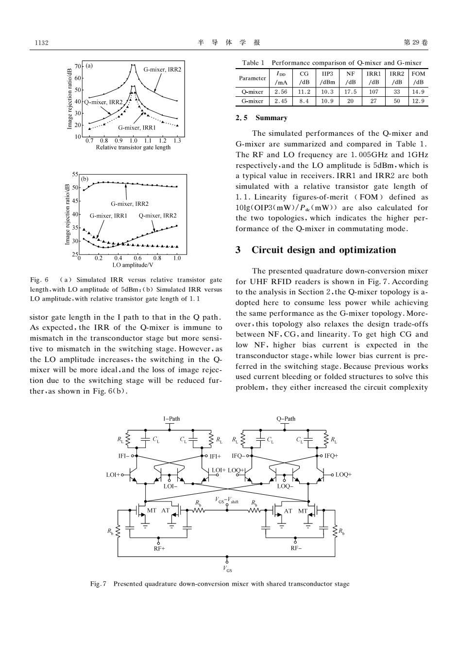
1132 半导体学报 第29卷 ,70(a) Table 1 Performance comparison of O-mixer and G-mixer G-mixer,IRR2 60 Parameter CG IIP3 NF IRR1 IRR2 FOM /mA /dB /dBm /dB /dB /dB /dB 50 Q-mixer 2.5611.2 10.3 17.51073314.9 40 Q-mixer,IRR2 G-mixer 2.45 8.4 10.9 20 27 5012.9 30 2.5 Summary 20 … G-mixer,IRRI 10 The simulated performances of the Q-mixer and 0.70.80.91.01.11.21.3 Relative transistor gate length G-mixer are summarized and compared in Table 1. The RF and LO frequency are 1.005GHz and 1GHz respectively,and the LO amplitude is 5dBm,which is 55 (b) a typical value in receivers.IRRI and IRR2 are both 50 simulated with a relative transistor gate length of 1.1.Linearity figures-of-merit (FOM)defined as G-mixer,IRR2 10lg(OIP3(mW)/Pde(mW))are also calculated for 40 G-mixer.IRRI Q-mixer,IRR2 the two topologies,which indicates the higher per- formance of the Q-mixer in commutating mode. 30 在AAAA-AA-AAA-A 3 Circuit design and optimization 0.2 0.40.60.8 1.0 LO amplitude/V The presented quadrature down-conversion mixer Fig.6 (a)Simulated IRR versus relative transistor gate for UHF RFID readers is shown in Fig.7.According length.with LO amplitude of 5dBm:(b)Simulated IRR versus to the analysis in Section 2,the Q-mixer topology is a- LO amplitude,with relative transistor gate length of 1.I dopted here to consume less power while achieving sistor gate length in the I path to that in the Q path. the same performance as the G-mixer topology.More- As expected,the IRR of the Q-mixer is immune to over,this topology also relaxes the design trade-offs mismatch in the transconductor stage but more sensi- between NF,CG,and linearity.To get high CG and tive to mismatch in the switching stage.However,as low NF,higher bias current is expected in the the LO amplitude increases,the switching in the O- transconductor stage,while lower bias current is pre- mixer will be more ideal,and the loss of image rejec- ferred in the switching stage.Because previous works tion due to the switching stage will be reduced fur- used current bleeding or folded structures to solve this ther,as shown in Fig.6(b). problem,they either increased the circuit complexity I-Path Q-Path IFL-o IFQ+ LOI+o- LOQ LOQ RF- G Fig.7 Presented quadrature down-conversion mixer with shared transconductor stage
半 导 体 学 报 第29卷 犉犻犵.6 (犪)犛犻犿狌犾犪狋犲犱 犐犚犚 狏犲狉狊狌狊狉犲犾犪狋犻狏犲狋狉犪狀狊犻狊狋狅狉 犵犪狋犲 犾犲狀犵狋犺,狑犻狋犺犔犗犪犿狆犾犻狋狌犱犲狅犳5犱犅犿;(犫)犛犻犿狌犾犪狋犲犱犐犚犚狏犲狉狊狌狊 犔犗犪犿狆犾犻狋狌犱犲,狑犻狋犺狉犲犾犪狋犻狏犲狋狉犪狀狊犻狊狋狅狉犵犪狋犲犾犲狀犵狋犺狅犳11 狊犻狊狋狅狉犵犪狋犲犾犲狀犵狋犺犻狀狋犺犲犐狆犪狋犺狋狅狋犺犪狋犻狀狋犺犲犙狆犪狋犺. 犃狊犲狓狆犲犮狋犲犱,狋犺犲犐犚犚 狅犳狋犺犲 犙犿犻狓犲狉犻狊犻犿犿狌狀犲狋狅 犿犻狊犿犪狋犮犺犻狀狋犺犲狋狉犪狀狊犮狅狀犱狌犮狋狅狉狊狋犪犵犲犫狌狋犿狅狉犲狊犲狀狊犻 狋犻狏犲狋狅 犿犻狊犿犪狋犮犺犻狀狋犺犲狊狑犻狋犮犺犻狀犵狊狋犪犵犲.犎狅狑犲狏犲狉,犪狊 狋犺犲犔犗 犪犿狆犾犻狋狌犱犲犻狀犮狉犲犪狊犲狊,狋犺犲狊狑犻狋犮犺犻狀犵犻狀狋犺犲 犙 犿犻狓犲狉狑犻犾犾犫犲犿狅狉犲犻犱犲犪犾,犪狀犱狋犺犲犾狅狊狊狅犳犻犿犪犵犲狉犲犼犲犮 狋犻狅狀犱狌犲狋狅狋犺犲狊狑犻狋犮犺犻狀犵狊狋犪犵犲 狑犻犾犾犫犲狉犲犱狌犮犲犱犳狌狉 狋犺犲狉,犪狊狊犺狅狑狀犻狀犉犻犵6(犫). 犜犪犫犾犲1 犘犲狉犳狅狉犿犪狀犮犲犮狅犿狆犪狉犻狊狅狀狅犳犙犿犻狓犲狉犪狀犱犌犿犻狓犲狉 犘犪狉犪犿犲狋犲狉 犐犇犇 /犿犃 犆犌 /犱犅 犐犐犘3 /犱犅犿 犖犉 /犱犅 犐犚犚1 /犱犅 犐犚犚2 /犱犅 犉犗犕 /犱犅 犙犿犻狓犲狉 2.56 11.2 10.3 17.5 107 33 14.9 犌犿犻狓犲狉 2.45 8.4 10.9 20 27 50 12.9 2.5 犛狌犿犿犪狉狔 犜犺犲狊犻犿狌犾犪狋犲犱狆犲狉犳狅狉犿犪狀犮犲狊狅犳狋犺犲犙犿犻狓犲狉犪狀犱 犌犿犻狓犲狉犪狉犲狊狌犿犿犪狉犻狕犲犱犪狀犱犮狅犿狆犪狉犲犱犻狀 犜犪犫犾犲1. 犜犺犲犚犉犪狀犱犔犗犳狉犲狇狌犲狀犮狔犪狉犲1005犌犎狕犪狀犱1犌犎狕 狉犲狊狆犲犮狋犻狏犲犾狔,犪狀犱狋犺犲犔犗犪犿狆犾犻狋狌犱犲犻狊5犱犅犿,狑犺犻犮犺犻狊 犪狋狔狆犻犮犪犾狏犪犾狌犲犻狀狉犲犮犲犻狏犲狉狊.犐犚犚1犪狀犱犐犚犚2犪狉犲犫狅狋犺 狊犻犿狌犾犪狋犲犱 狑犻狋犺 犪狉犲犾犪狋犻狏犲狋狉犪狀狊犻狊狋狅狉犵犪狋犲犾犲狀犵狋犺 狅犳 11.犔犻狀犲犪狉犻狋狔 犳犻犵狌狉犲狊狅犳犿犲狉犻狋 (犉犗犕)犱犲犳犻狀犲犱 犪狊 10犾犵(犗犐犘3(犿犠)/犘犱犮(犿犠))犪狉犲 犪犾狊狅 犮犪犾犮狌犾犪狋犲犱犳狅狉 狋犺犲狋狑狅狋狅狆狅犾狅犵犻犲狊,狑犺犻犮犺犻狀犱犻犮犪狋犲狊狋犺犲犺犻犵犺犲狉狆犲狉 犳狅狉犿犪狀犮犲狅犳狋犺犲犙犿犻狓犲狉犻狀犮狅犿犿狌狋犪狋犻狀犵犿狅犱犲. 3 犆犻狉犮狌犻狋犱犲狊犻犵狀犪狀犱狅狆狋犻犿犻狕犪狋犻狅狀 犜犺犲狆狉犲狊犲狀狋犲犱狇狌犪犱狉犪狋狌狉犲犱狅狑狀犮狅狀狏犲狉狊犻狅狀犿犻狓犲狉 犳狅狉犝犎犉犚犉犐犇狉犲犪犱犲狉狊犻狊狊犺狅狑狀犻狀犉犻犵7.犃犮犮狅狉犱犻狀犵 狋狅狋犺犲犪狀犪犾狔狊犻狊犻狀犛犲犮狋犻狅狀2,狋犺犲犙犿犻狓犲狉狋狅狆狅犾狅犵狔犻狊犪 犱狅狆狋犲犱犺犲狉犲狋狅犮狅狀狊狌犿犲犾犲狊狊狆狅狑犲狉 狑犺犻犾犲犪犮犺犻犲狏犻狀犵 狋犺犲狊犪犿犲狆犲狉犳狅狉犿犪狀犮犲犪狊狋犺犲犌犿犻狓犲狉狋狅狆狅犾狅犵狔.犕狅狉犲 狅狏犲狉,狋犺犻狊狋狅狆狅犾狅犵狔犪犾狊狅狉犲犾犪狓犲狊狋犺犲犱犲狊犻犵狀狋狉犪犱犲狅犳犳狊 犫犲狋狑犲犲狀犖犉,犆犌,犪狀犱犾犻狀犲犪狉犻狋狔.犜狅犵犲狋犺犻犵犺 犆犌 犪狀犱 犾狅狑 犖犉,犺犻犵犺犲狉 犫犻犪狊 犮狌狉狉犲狀狋 犻狊 犲狓狆犲犮狋犲犱 犻狀 狋犺犲 狋狉犪狀狊犮狅狀犱狌犮狋狅狉狊狋犪犵犲,狑犺犻犾犲犾狅狑犲狉犫犻犪狊犮狌狉狉犲狀狋犻狊狆狉犲 犳犲狉狉犲犱犻狀狋犺犲狊狑犻狋犮犺犻狀犵狊狋犪犵犲.犅犲犮犪狌狊犲狆狉犲狏犻狅狌狊狑狅狉犽狊 狌狊犲犱犮狌狉狉犲狀狋犫犾犲犲犱犻狀犵狅狉犳狅犾犱犲犱狊狋狉狌犮狋狌狉犲狊狋狅狊狅犾狏犲狋犺犻狊 狆狉狅犫犾犲犿,狋犺犲狔犲犻狋犺犲狉犻狀犮狉犲犪狊犲犱狋犺犲犮犻狉犮狌犻狋犮狅犿狆犾犲狓犻狋狔 犉犻犵.7 犘狉犲狊犲狀狋犲犱狇狌犪犱狉犪狋狌狉犲犱狅狑狀犮狅狀狏犲狉狊犻狅狀犿犻狓犲狉狑犻狋犺狊犺犪狉犲犱狋狉犪狀狊犮狅狀犱狌犮狋狅狉狊狋犪犵犲 1132
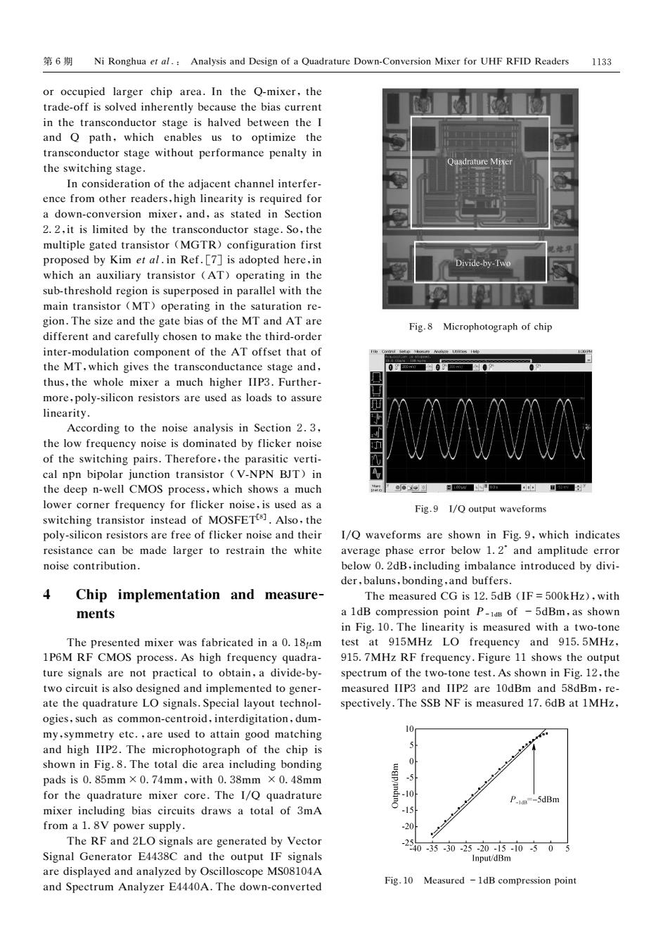
6 Ni Ronghua et al.:Analysis and Design of a Quadrature Down-Conversion Mixer for UHF RFID Readers 1133 or occupied larger chip area.In the Q-mixer,the trade-off is solved inherently because the bias current in the transconductor stage is halved between the I and Q path,which enables us to optimize the transconductor stage without performance penalty in the switching stage. In consideration of the adjacent channel interfer- ence from other readers,high linearity is required for a down-conversion mixer,and,as stated in Section 2.2,it is limited by the transconductor stage.So,the multiple gated transistor (MGTR)configuration first proposed by Kim et al.in Ref.[7]is adopted here,in Divide-by-Twe which an auxiliary transistor (AT)operating in the sub-threshold region is superposed in parallel with the main transistor (MT)operating in the saturation re- gion.The size and the gate bias of the MT and AT are Fig.8 Microphotograph of chip different and carefully chosen to make the third-order inter-modulation component of the AT offset that of the MT,which gives the transconductance stage and, thus,the whole mixer a much higher IIP3.Further- more,poly-silicon resistors are used as loads to assure linearity. According to the noise analysis in Section 2.3, the low frequency noise is dominated by flicker noise of the switching pairs.Therefore,the parasitic verti- cal npn bipolar junction transistor (V-NPN BJT)in the deep n-well CMOS process,which shows a much @o3如浏 0o■ lower corner frequency for flicker noise,is used as a Fig.9 I/Q output waveforms switching transistor instead of MOSFETs].Also,the poly-silicon resistors are free of flicker noise and their I/Q waveforms are shown in Fig.9,which indicates resistance can be made larger to restrain the white average phase error below 1.2'and amplitude error noise contribution. below 0.2dB,including imbalance introduced by divi- der,baluns,bonding,and buffers. 4 Chip implementation and measure- The measured CG is 12.5dB (IF=500kHz),with ments a 1dB compression point P-idB of -5dBm,as shown in Fig.10.The linearity is measured with a two-tone The presented mixer was fabricated in a 0.18um test at 915MHz LO frequency and 915.5MHz, 1P6M RF CMOS process.As high frequency quadra- 915.7MHz RF frequency.Figure 11 shows the output ture signals are not practical to obtain,a divide-by- spectrum of the two-tone test.As shown in Fig.12,the two circuit is also designed and implemented to gener- measured IIP3 and IIP2 are 10dBm and 58dBm,re- ate the quadrature LO signals.Special layout technol- spectively.The SSB NF is measured 17.6dB at 1MHz, ogies,such as common-centroid,interdigitation,dum- my,symmetry etc.,are used to attain good matching 10 and high IIP2.The microphotograph of the chip is shown in Fig.8.The total die area including bonding pads is0.85mm×0.74mm,with0.38mm×0.48mm -5 for the quadrature mixer core.The 1/Q quadrature P.idm--5dBm mixer including bias circuits draws a total of 3mA -15 from a 1.8V power supply. -20 The RF and 2LO signals are generated by Vector Signal Generator E4438C and the output IF signals -254035-3025-2010505 Input/dBm are displayed and analyzed by Oscilloscope MS08104A and Spectrum Analyzer E4440A.The down-converted Fig.10 Measured -1dB compression point
第6期 犖犻犚狅狀犵犺狌犪犲狋犪犾.: 犃狀犪犾狔狊犻狊犪狀犱犇犲狊犻犵狀狅犳犪犙狌犪犱狉犪狋狌狉犲犇狅狑狀犆狅狀狏犲狉狊犻狅狀犕犻狓犲狉犳狅狉犝犎犉犚犉犐犇 犚犲犪犱犲狉狊 狅狉狅犮犮狌狆犻犲犱犾犪狉犵犲狉犮犺犻狆 犪狉犲犪.犐狀 狋犺犲 犙犿犻狓犲狉,狋犺犲 狋狉犪犱犲狅犳犳犻狊狊狅犾狏犲犱犻狀犺犲狉犲狀狋犾狔犫犲犮犪狌狊犲狋犺犲犫犻犪狊犮狌狉狉犲狀狋 犻狀狋犺犲狋狉犪狀狊犮狅狀犱狌犮狋狅狉狊狋犪犵犲犻狊犺犪犾狏犲犱犫犲狋狑犲犲狀狋犺犲犐 犪狀犱 犙 狆犪狋犺,狑犺犻犮犺 犲狀犪犫犾犲狊 狌狊 狋狅 狅狆狋犻犿犻狕犲 狋犺犲 狋狉犪狀狊犮狅狀犱狌犮狋狅狉狊狋犪犵犲狑犻狋犺狅狌狋狆犲狉犳狅狉犿犪狀犮犲狆犲狀犪犾狋狔犻狀 狋犺犲狊狑犻狋犮犺犻狀犵狊狋犪犵犲. 犐狀犮狅狀狊犻犱犲狉犪狋犻狅狀狅犳狋犺犲犪犱犼犪犮犲狀狋犮犺犪狀狀犲犾犻狀狋犲狉犳犲狉 犲狀犮犲犳狉狅犿狅狋犺犲狉狉犲犪犱犲狉狊,犺犻犵犺犾犻狀犲犪狉犻狋狔犻狊狉犲狇狌犻狉犲犱犳狅狉 犪犱狅狑狀犮狅狀狏犲狉狊犻狅狀 犿犻狓犲狉,犪狀犱,犪狊狊狋犪狋犲犱犻狀 犛犲犮狋犻狅狀 22,犻狋犻狊犾犻犿犻狋犲犱犫狔狋犺犲狋狉犪狀狊犮狅狀犱狌犮狋狅狉狊狋犪犵犲.犛狅,狋犺犲 犿狌犾狋犻狆犾犲犵犪狋犲犱狋狉犪狀狊犻狊狋狅狉(犕犌犜犚)犮狅狀犳犻犵狌狉犪狋犻狅狀犳犻狉狊狋 狆狉狅狆狅狊犲犱犫狔犓犻犿犲狋犪犾.犻狀犚犲犳.[7]犻狊犪犱狅狆狋犲犱犺犲狉犲,犻狀 狑犺犻犮犺犪狀犪狌狓犻犾犻犪狉狔狋狉犪狀狊犻狊狋狅狉 (犃犜)狅狆犲狉犪狋犻狀犵犻狀狋犺犲 狊狌犫狋犺狉犲狊犺狅犾犱狉犲犵犻狅狀犻狊狊狌狆犲狉狆狅狊犲犱犻狀狆犪狉犪犾犾犲犾狑犻狋犺狋犺犲 犿犪犻狀狋狉犪狀狊犻狊狋狅狉(犕犜)狅狆犲狉犪狋犻狀犵犻狀狋犺犲狊犪狋狌狉犪狋犻狅狀狉犲 犵犻狅狀.犜犺犲狊犻狕犲犪狀犱狋犺犲犵犪狋犲犫犻犪狊狅犳狋犺犲犕犜犪狀犱犃犜犪狉犲 犱犻犳犳犲狉犲狀狋犪狀犱犮犪狉犲犳狌犾犾狔犮犺狅狊犲狀狋狅犿犪犽犲狋犺犲狋犺犻狉犱狅狉犱犲狉 犻狀狋犲狉犿狅犱狌犾犪狋犻狅狀犮狅犿狆狅狀犲狀狋狅犳狋犺犲犃犜狅犳犳狊犲狋狋犺犪狋狅犳 狋犺犲犕犜,狑犺犻犮犺犵犻狏犲狊狋犺犲狋狉犪狀狊犮狅狀犱狌犮狋犪狀犮犲狊狋犪犵犲犪狀犱, 狋犺狌狊,狋犺犲 狑犺狅犾犲 犿犻狓犲狉犪 犿狌犮犺犺犻犵犺犲狉犐犐犘3.犉狌狉狋犺犲狉 犿狅狉犲,狆狅犾狔狊犻犾犻犮狅狀狉犲狊犻狊狋狅狉狊犪狉犲狌狊犲犱犪狊犾狅犪犱狊狋狅犪狊狊狌狉犲 犾犻狀犲犪狉犻狋狔. 犃犮犮狅狉犱犻狀犵狋狅狋犺犲狀狅犻狊犲犪狀犪犾狔狊犻狊犻狀犛犲犮狋犻狅狀2.3, 狋犺犲犾狅狑犳狉犲狇狌犲狀犮狔狀狅犻狊犲犻狊犱狅犿犻狀犪狋犲犱犫狔犳犾犻犮犽犲狉狀狅犻狊犲 狅犳狋犺犲狊狑犻狋犮犺犻狀犵狆犪犻狉狊.犜犺犲狉犲犳狅狉犲,狋犺犲狆犪狉犪狊犻狋犻犮狏犲狉狋犻 犮犪犾狀狆狀犫犻狆狅犾犪狉犼狌狀犮狋犻狅狀狋狉犪狀狊犻狊狋狅狉 (犞犖犘犖 犅犑犜)犻狀 狋犺犲犱犲犲狆狀狑犲犾犾犆犕犗犛狆狉狅犮犲狊狊,狑犺犻犮犺狊犺狅狑狊犪 犿狌犮犺 犾狅狑犲狉犮狅狉狀犲狉犳狉犲狇狌犲狀犮狔犳狅狉犳犾犻犮犽犲狉狀狅犻狊犲,犻狊狌狊犲犱犪狊犪 狊狑犻狋犮犺犻狀犵狋狉犪狀狊犻狊狋狅狉犻狀狊狋犲犪犱狅犳 犕犗犛犉犈犜[8] .犃犾狊狅,狋犺犲 狆狅犾狔狊犻犾犻犮狅狀狉犲狊犻狊狋狅狉狊犪狉犲犳狉犲犲狅犳犳犾犻犮犽犲狉狀狅犻狊犲犪狀犱狋犺犲犻狉 狉犲狊犻狊狋犪狀犮犲犮犪狀犫犲 犿犪犱犲犾犪狉犵犲狉狋狅狉犲狊狋狉犪犻狀狋犺犲 狑犺犻狋犲 狀狅犻狊犲犮狅狀狋狉犻犫狌狋犻狅狀. 4 犆犺犻狆犻犿狆犾犲犿犲狀狋犪狋犻狅狀 犪狀犱 犿犲犪狊狌狉犲 犿犲狀狋狊 犜犺犲狆狉犲狊犲狀狋犲犱犿犻狓犲狉狑犪狊犳犪犫狉犻犮犪狋犲犱犻狀犪018μ犿 1犘6犕 犚犉犆犕犗犛狆狉狅犮犲狊狊.犃狊犺犻犵犺犳狉犲狇狌犲狀犮狔狇狌犪犱狉犪 狋狌狉犲狊犻犵狀犪犾狊犪狉犲狀狅狋狆狉犪犮狋犻犮犪犾狋狅狅犫狋犪犻狀,犪犱犻狏犻犱犲犫狔 狋狑狅犮犻狉犮狌犻狋犻狊犪犾狊狅犱犲狊犻犵狀犲犱犪狀犱犻犿狆犾犲犿犲狀狋犲犱狋狅犵犲狀犲狉 犪狋犲狋犺犲狇狌犪犱狉犪狋狌狉犲犔犗狊犻犵狀犪犾狊.犛狆犲犮犻犪犾犾犪狔狅狌狋狋犲犮犺狀狅犾 狅犵犻犲狊,狊狌犮犺犪狊犮狅犿犿狅狀犮犲狀狋狉狅犻犱,犻狀狋犲狉犱犻犵犻狋犪狋犻狅狀,犱狌犿 犿狔,狊狔犿犿犲狋狉狔犲狋犮.,犪狉犲狌狊犲犱狋狅犪狋狋犪犻狀犵狅狅犱 犿犪狋犮犺犻狀犵 犪狀犱犺犻犵犺犐犐犘2.犜犺犲 犿犻犮狉狅狆犺狅狋狅犵狉犪狆犺狅犳狋犺犲犮犺犻狆犻狊 狊犺狅狑狀犻狀犉犻犵.8.犜犺犲狋狅狋犪犾犱犻犲犪狉犲犪犻狀犮犾狌犱犻狀犵犫狅狀犱犻狀犵 狆犪犱狊犻狊085犿犿×074犿犿,狑犻狋犺038犿犿 ×048犿犿 犳狅狉狋犺犲狇狌犪犱狉犪狋狌狉犲 犿犻狓犲狉犮狅狉犲.犜犺犲犐/犙 狇狌犪犱狉犪狋狌狉犲 犿犻狓犲狉犻狀犮犾狌犱犻狀犵犫犻犪狊犮犻狉犮狌犻狋狊犱狉犪狑狊犪狋狅狋犪犾狅犳3犿犃 犳狉狅犿犪18犞狆狅狑犲狉狊狌狆狆犾狔. 犜犺犲犚犉犪狀犱2犔犗狊犻犵狀犪犾狊犪狉犲犵犲狀犲狉犪狋犲犱犫狔犞犲犮狋狅狉 犛犻犵狀犪犾犌犲狀犲狉犪狋狅狉犈4438犆 犪狀犱狋犺犲狅狌狋狆狌狋犐犉狊犻犵狀犪犾狊 犪狉犲犱犻狊狆犾犪狔犲犱犪狀犱犪狀犪犾狔狕犲犱犫狔犗狊犮犻犾犾狅狊犮狅狆犲犕犛08104犃 犪狀犱犛狆犲犮狋狉狌犿 犃狀犪犾狔狕犲狉犈4440犃.犜犺犲犱狅狑狀犮狅狀狏犲狉狋犲犱 犉犻犵.8 犕犻犮狉狅狆犺狅狋狅犵狉犪狆犺狅犳犮犺犻狆 犉犻犵.9 犐/犙狅狌狋狆狌狋狑犪狏犲犳狅狉犿狊 犐/犙 狑犪狏犲犳狅狉犿狊犪狉犲狊犺狅狑狀犻狀犉犻犵9,狑犺犻犮犺犻狀犱犻犮犪狋犲狊 犪狏犲狉犪犵犲狆犺犪狊犲犲狉狉狅狉犫犲犾狅狑12°犪狀犱犪犿狆犾犻狋狌犱犲犲狉狉狅狉 犫犲犾狅狑02犱犅,犻狀犮犾狌犱犻狀犵犻犿犫犪犾犪狀犮犲犻狀狋狉狅犱狌犮犲犱犫狔犱犻狏犻 犱犲狉,犫犪犾狌狀狊,犫狅狀犱犻狀犵,犪狀犱犫狌犳犳犲狉狊. 犜犺犲犿犲犪狊狌狉犲犱犆犌犻狊125犱犅 (犐犉=500犽犎狕),狑犻狋犺 犪1犱犅犮狅犿狆狉犲狊狊犻狅狀狆狅犻狀狋犘-1犱犅 狅犳 -5犱犅犿,犪狊狊犺狅狑狀 犻狀犉犻犵10.犜犺犲犾犻狀犲犪狉犻狋狔犻狊犿犲犪狊狌狉犲犱狑犻狋犺犪狋狑狅狋狅狀犲 狋犲狊狋 犪狋 915犕犎狕 犔犗 犳狉犲狇狌犲狀犮狔 犪狀犱 9155犕犎狕, 9157犕犎狕犚犉犳狉犲狇狌犲狀犮狔.犉犻犵狌狉犲11狊犺狅狑狊狋犺犲狅狌狋狆狌狋 狊狆犲犮狋狉狌犿狅犳狋犺犲狋狑狅狋狅狀犲狋犲狊狋.犃狊狊犺狅狑狀犻狀犉犻犵12,狋犺犲 犿犲犪狊狌狉犲犱犐犐犘3犪狀犱犐犐犘2犪狉犲10犱犅犿 犪狀犱58犱犅犿,狉犲 狊狆犲犮狋犻狏犲犾狔.犜犺犲犛犛犅犖犉犻狊犿犲犪狊狌狉犲犱176犱犅犪狋1犕犎狕, 犉犻犵.10 犕犲犪狊狌狉犲犱-1犱犅犮狅犿狆狉犲狊狊犻狅狀狆狅犻狀狋 1133
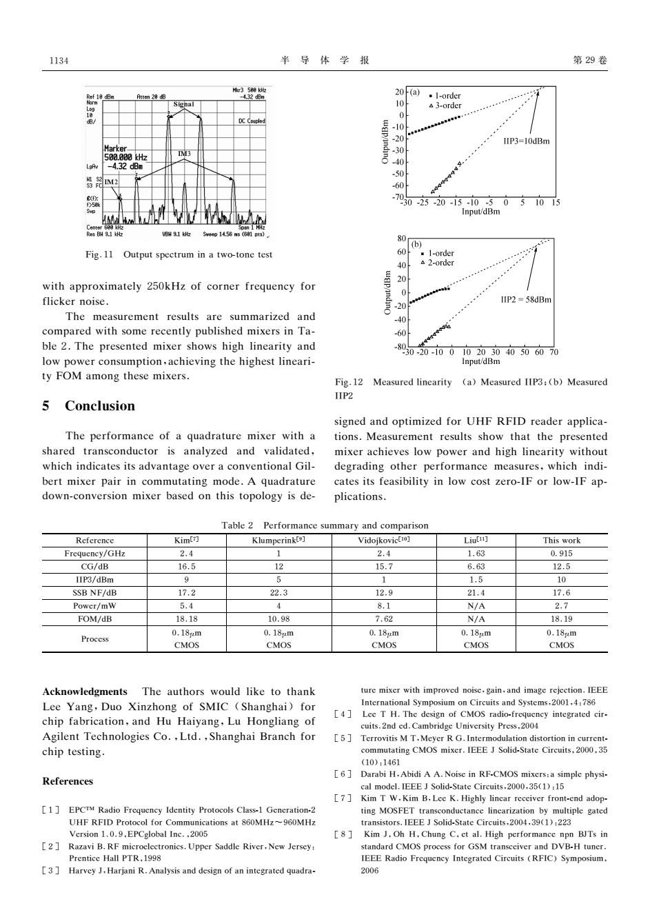
1134 半导体学报 第29卷 20(a) Atten 28 dB -order Signal 10 A3-order 0 DC Couple -10 -20 IIP3=10dBm Marker -30 500.800kHz 3 LgAv -4.32dBm -40 50 -60 -7 30-25-20-15-10-5051015 Input/dBm E酬91kh S414.56ms(G810时3) 80 ” Fig.11 Output spectrum in a two-tone test 60 .1-order 40 A 2-order 20 with approximately 250kHz of corner frequency for 0 flicker noise. IIP2 =58dBm -20 The measurement results are summarized and 40 compared with some recently published mixers in Ta- -60 ble 2.The presented mixer shows high linearity and low power consumption,achieving the highest lineari- -8050-20-i0010203040506070 Input/dBm ty FOM among these mixers. Fig.12 Measured linearity (a)Measured IIP3:(b)Measured 1IP2 Conclusion signed and optimized for UHF RFID reader applica- The performance of a quadrature mixer with a tions.Measurement results show that the presented shared transconductor is analyzed and validated, mixer achieves low power and high linearity without which indicates its advantage over a conventional Gil- degrading other performance measures,which indi- bert mixer pair in commutating mode.A quadrature cates its feasibility in low cost zero-IF or low-IF ap- down-conversion mixer based on this topology is de- plications. Table 2 Performance summary and comparison Reference Kim[ Klumperinkts] Vidojkovic[10] Liuti] This work Frequency/GHz 2.4 1 2.4 1.63 0.915 CG/dB 16.5 12 15.7 6.63 12.5 IIP3/dBm 9 5 1 1.5 10 SSB NF/dB 17.2 22.3 12.9 21.4 17.6 Power/mW 5.4 4 8.1 N/A 2.7 FOM/dB 18.18 10.98 7.62 N/A 18.19 0.18m 0.18m 0.18m 0.18m 0.18m Process CMOS CMOS CMOS CMOS CMOS Acknowledgments The authors would like to thank ture mixer with improved noise,gain,and image rejection.IEEE Lee Yang,Duo Xinzhong of SMIC (Shanghai)for International Symposium on Circuits and Systems,2001.4:786 [4] Lee T H.The design of CMOS radio-frequency integrated cir- chip fabrication,and Hu Haiyang,Lu Hongliang of cuits.2nd ed.Cambridge University Press.2004 Agilent Technologies Co.,Ltd.,Shanghai Branch for [5]Terrovitis M T,Meyer R G.Intermodulation distortion in current- chip testing. commutating CMOS mixer.IEEE J Solid-State Circuits,2000,35 (10):1461 [6] Darabi H.Abidi AA.Noise in RF-CMOS mixers:a simple physi- References cal model.IEEE J Solid-State Circuits.2000.35(1):15 [7]Kim T W.Kim B.Lec K.Highly lincar receiver front-end adop- [1]EPCTM Radio Frequency Identity Protocols Class-1 Generation-2 ting MOSFET transconductance linearization by multiple gated UHF RFID Protocol for Communications at 860MHz~960MHz transistors.IEEE J Solid-State Circuits,2004.39(1):223 Version 1.0.9.EPCglobal Inc.,2005 [8]Kim J.Oh H.Chung C.et al.High performance npn BITs in [2]Razavi B.RF microclectronics.Upper Saddle River.New Jersey: standard CMOS process for GSM transceiver and DVB-H tuner Prentice Hall PTR,1998 IEEE Radio Frequency Integrated Circuits(RFIC)Symposium. 3 Harvey J,Harjani R.Analysis and design of an integrated quadra- 2006
半 导 体 学 报 第29卷 犉犻犵.11 犗狌狋狆狌狋狊狆犲犮狋狉狌犿犻狀犪狋狑狅狋狅狀犲狋犲狊狋 狑犻狋犺犪狆狆狉狅狓犻犿犪狋犲犾狔250犽犎狕狅犳犮狅狉狀犲狉犳狉犲狇狌犲狀犮狔犳狅狉 犳犾犻犮犽犲狉狀狅犻狊犲. 犜犺犲 犿犲犪狊狌狉犲犿犲狀狋狉犲狊狌犾狋狊 犪狉犲 狊狌犿犿犪狉犻狕犲犱 犪狀犱 犮狅犿狆犪狉犲犱狑犻狋犺狊狅犿犲狉犲犮犲狀狋犾狔狆狌犫犾犻狊犺犲犱犿犻狓犲狉狊犻狀犜犪 犫犾犲2.犜犺犲狆狉犲狊犲狀狋犲犱 犿犻狓犲狉狊犺狅狑狊犺犻犵犺犾犻狀犲犪狉犻狋狔犪狀犱 犾狅狑狆狅狑犲狉犮狅狀狊狌犿狆狋犻狅狀,犪犮犺犻犲狏犻狀犵狋犺犲犺犻犵犺犲狊狋犾犻狀犲犪狉犻 狋狔犉犗犕犪犿狅狀犵狋犺犲狊犲犿犻狓犲狉狊. 5 犆狅狀犮犾狌狊犻狅狀 犜犺犲狆犲狉犳狅狉犿犪狀犮犲狅犳犪狇狌犪犱狉犪狋狌狉犲 犿犻狓犲狉狑犻狋犺犪 狊犺犪狉犲犱 狋狉犪狀狊犮狅狀犱狌犮狋狅狉 犻狊 犪狀犪犾狔狕犲犱 犪狀犱 狏犪犾犻犱犪狋犲犱, 狑犺犻犮犺犻狀犱犻犮犪狋犲狊犻狋狊犪犱狏犪狀狋犪犵犲狅狏犲狉犪犮狅狀狏犲狀狋犻狅狀犪犾犌犻犾 犫犲狉狋犿犻狓犲狉狆犪犻狉犻狀犮狅犿犿狌狋犪狋犻狀犵 犿狅犱犲.犃 狇狌犪犱狉犪狋狌狉犲 犱狅狑狀犮狅狀狏犲狉狊犻狅狀 犿犻狓犲狉犫犪狊犲犱狅狀狋犺犻狊狋狅狆狅犾狅犵狔犻狊犱犲 犉犻犵.12 犕犲犪狊狌狉犲犱犾犻狀犲犪狉犻狋狔 (犪)犕犲犪狊狌狉犲犱犐犐犘3;(犫)犕犲犪狊狌狉犲犱 犐犐犘2 狊犻犵狀犲犱犪狀犱狅狆狋犻犿犻狕犲犱犳狅狉犝犎犉 犚犉犐犇狉犲犪犱犲狉犪狆狆犾犻犮犪 狋犻狅狀狊.犕犲犪狊狌狉犲犿犲狀狋狉犲狊狌犾狋狊狊犺狅狑 狋犺犪狋狋犺犲狆狉犲狊犲狀狋犲犱 犿犻狓犲狉犪犮犺犻犲狏犲狊犾狅狑狆狅狑犲狉犪狀犱犺犻犵犺犾犻狀犲犪狉犻狋狔狑犻狋犺狅狌狋 犱犲犵狉犪犱犻狀犵狅狋犺犲狉狆犲狉犳狅狉犿犪狀犮犲 犿犲犪狊狌狉犲狊,狑犺犻犮犺犻狀犱犻 犮犪狋犲狊犻狋狊犳犲犪狊犻犫犻犾犻狋狔犻狀犾狅狑犮狅狊狋狕犲狉狅犐犉狅狉犾狅狑犐犉犪狆 狆犾犻犮犪狋犻狅狀狊. 犜犪犫犾犲2 犘犲狉犳狅狉犿犪狀犮犲狊狌犿犿犪狉狔犪狀犱犮狅犿狆犪狉犻狊狅狀 犚犲犳犲狉犲狀犮犲 犓犻犿[7] 犓犾狌犿狆犲狉犻狀犽[9] 犞犻犱狅犼犽狅狏犻犮[10] 犔犻狌[11] 犜犺犻狊狑狅狉犽 犉狉犲狇狌犲狀犮狔/犌犎狕 2.4 1 2.4 1.63 0915 犆犌/犱犅 16.5 12 15.7 6.63 12.5 犐犐犘3/犱犅犿 9 5 1 1.5 10 犛犛犅犖犉/犱犅 17.2 22.3 12.9 21.4 17.6 犘狅狑犲狉/犿犠 5.4 4 8.1 犖/犃 2.7 犉犗犕/犱犅 18.18 10.98 7.62 犖/犃 18.19 犘狉狅犮犲狊狊 0.18μ犿 犆犕犗犛 018μ犿 犆犕犗犛 018μ犿 犆犕犗犛 018μ犿 犆犕犗犛 0.18μ犿 犆犕犗犛 犃犮犽狀狅狑犾犲犱犵犿犲狀狋狊 犜犺犲犪狌狋犺狅狉狊狑狅狌犾犱犾犻犽犲狋狅狋犺犪狀犽 犔犲犲 犢犪狀犵,犇狌狅 犡犻狀狕犺狅狀犵狅犳犛犕犐犆 (犛犺犪狀犵犺犪犻)犳狅狉 犮犺犻狆犳犪犫狉犻犮犪狋犻狅狀,犪狀犱 犎狌 犎犪犻狔犪狀犵,犔狌 犎狅狀犵犾犻犪狀犵狅犳 犃犵犻犾犲狀狋犜犲犮犺狀狅犾狅犵犻犲狊犆狅.,犔狋犱.,犛犺犪狀犵犺犪犻犅狉犪狀犮犺犳狅狉 犮犺犻狆狋犲狊狋犻狀犵. 犚犲犳犲狉犲狀犮犲狊 [1] 犈犘犆犜犕 犚犪犱犻狅犉狉犲狇狌犲狀犮狔犐犱犲狀狋犻狋狔犘狉狅狋狅犮狅犾狊犆犾犪狊狊1犌犲狀犲狉犪狋犻狅狀2 犝犎犉犚犉犐犇犘狉狅狋狅犮狅犾犳狅狉犆狅犿犿狌狀犻犮犪狋犻狅狀狊犪狋860犕犎狕~960犕犎狕 犞犲狉狊犻狅狀1.0.9,犈犘犆犵犾狅犫犪犾犐狀犮.,2005 [2] 犚犪狕犪狏犻犅.犚犉犿犻犮狉狅犲犾犲犮狋狉狅狀犻犮狊.犝狆狆犲狉犛犪犱犱犾犲犚犻狏犲狉,犖犲狑犑犲狉狊犲狔: 犘狉犲狀狋犻犮犲犎犪犾犾犘犜犚,1998 [3] 犎犪狉狏犲狔犑,犎犪狉犼犪狀犻犚.犃狀犪犾狔狊犻狊犪狀犱犱犲狊犻犵狀狅犳犪狀犻狀狋犲犵狉犪狋犲犱狇狌犪犱狉犪 狋狌狉犲犿犻狓犲狉狑犻狋犺犻犿狆狉狅狏犲犱狀狅犻狊犲,犵犪犻狀,犪狀犱犻犿犪犵犲狉犲犼犲犮狋犻狅狀.犐犈犈犈 犐狀狋犲狉狀犪狋犻狅狀犪犾犛狔犿狆狅狊犻狌犿狅狀犆犻狉犮狌犻狋狊犪狀犱犛狔狊狋犲犿狊,2001,4:786 [4] 犔犲犲犜 犎.犜犺犲犱犲狊犻犵狀狅犳犆犕犗犛狉犪犱犻狅犳狉犲狇狌犲狀犮狔犻狀狋犲犵狉犪狋犲犱犮犻狉 犮狌犻狋狊.2狀犱犲犱.犆犪犿犫狉犻犱犵犲犝狀犻狏犲狉狊犻狋狔犘狉犲狊狊,2004 [5] 犜犲狉狉狅狏犻狋犻狊犕犜,犕犲狔犲狉犚犌.犐狀狋犲狉犿狅犱狌犾犪狋犻狅狀犱犻狊狋狅狉狋犻狅狀犻狀犮狌狉狉犲狀狋 犮狅犿犿狌狋犪狋犻狀犵犆犕犗犛犿犻狓犲狉.犐犈犈犈犑犛狅犾犻犱犛狋犪狋犲犆犻狉犮狌犻狋狊,2000,35 (10):1461 [6] 犇犪狉犪犫犻犎,犃犫犻犱犻犃 犃.犖狅犻狊犲犻狀犚犉犆犕犗犛犿犻狓犲狉狊:犪狊犻犿狆犾犲狆犺狔狊犻 犮犪犾犿狅犱犲犾.犐犈犈犈犑犛狅犾犻犱犛狋犪狋犲犆犻狉犮狌犻狋狊,2000,35(1):15 [7] 犓犻犿 犜 犠,犓犻犿 犅,犔犲犲犓.犎犻犵犺犾狔犾犻狀犲犪狉狉犲犮犲犻狏犲狉犳狉狅狀狋犲狀犱犪犱狅狆 狋犻狀犵 犕犗犛犉犈犜狋狉犪狀狊犮狅狀犱狌犮狋犪狀犮犲犾犻狀犲犪狉犻狕犪狋犻狅狀犫狔 犿狌犾狋犻狆犾犲犵犪狋犲犱 狋狉犪狀狊犻狊狋狅狉狊.犐犈犈犈犑犛狅犾犻犱犛狋犪狋犲犆犻狉犮狌犻狋狊,2004,39(1):223 [8] 犓犻犿 犑,犗犺 犎,犆犺狌狀犵犆,犲狋犪犾.犎犻犵犺狆犲狉犳狅狉犿犪狀犮犲狀狆狀 犅犑犜狊犻狀 狊狋犪狀犱犪狉犱犆犕犗犛狆狉狅犮犲狊狊犳狅狉犌犛犕狋狉犪狀狊犮犲犻狏犲狉犪狀犱犇犞犅犎狋狌狀犲狉. 犐犈犈犈犚犪犱犻狅犉狉犲狇狌犲狀犮狔犐狀狋犲犵狉犪狋犲犱犆犻狉犮狌犻狋狊(犚犉犐犆)犛狔犿狆狅狊犻狌犿, 2006 1134
第6期 Ni Ronghua et al.Analysis and Design of a Quadrature Down-Conversion Mixer for UHF RFID Readers 1135 [9 Klumperink E A M.Louwsma S M,Wienk G J M.ct al.A CMOS switching mixer in 0.18-um CMOS.IEEE J Solid-State Circuits, switched transconductor mixer.IEEE J Solid-State Circuits.2004, 2005,40(6):1259 39(8):1231 [11]Liu L.Wang Z H.Analysis and design of a low-voltage RF CMOS [10]Vidojkovic V,Tang J.Roermund A H M.A low-voltage folded- mixer,.IEEE Trans Circuits SystⅡ,2006,53(3):212 一种用于超高频RFID阅读器的正交下变频混频器的分析与设计 倪熔华谈熙唐长文闵吴 (复旦大学专用集成电路与系统国家重点实验室,上海201203) 摘要:分析了共用跨导级的正交下变频混频器的性能,包括电压转换增益、线性度、噪声系数和镜象抑制比,分析表明其在电流开关 模式下比传统的Gilbert混频器对具有更好的性能.设计并优化了一个基于共用跨导级结构的用于超高频RFID阅读器的正交下变 频混频器.在915MHz频段上,该混频器测得12.5dB的转换增益,10dBm的IIP3,58dBm的IIP2和17.6dB的SSB噪声系数.芯片采 用0.18um1P6 M RF CMOS工艺实现,在1.8V的电源电压下仅消耗3mA电流. 关键词:正交混频器:共用跨导级:RFD阅读器:CMOS:低功耗:高线性度 EEACC:1250 中图分类号:TN43 文献标识码:A 文章编号:0253-4177(2008)06-1128-08 *国家高技术研究发展计划资助项目(批准号:2007AA01Z282) t通信作者,Email:zwtang@fudan.cdu.cn 2007-12.19收到,2008.01-31定稿 ©2008中国电子学会
第6期 犖犻犚狅狀犵犺狌犪犲狋犪犾.: 犃狀犪犾狔狊犻狊犪狀犱犇犲狊犻犵狀狅犳犪犙狌犪犱狉犪狋狌狉犲犇狅狑狀犆狅狀狏犲狉狊犻狅狀犕犻狓犲狉犳狅狉犝犎犉犚犉犐犇 犚犲犪犱犲狉狊 [9] 犓犾狌犿狆犲狉犻狀犽犈犃 犕,犔狅狌狑狊犿犪犛犕,犠犻犲狀犽犌犑犕,犲狋犪犾.犃犆犕犗犛 狊狑犻狋犮犺犲犱狋狉犪狀狊犮狅狀犱狌犮狋狅狉犿犻狓犲狉.犐犈犈犈犑犛狅犾犻犱犛狋犪狋犲犆犻狉犮狌犻狋狊,2004, 39(8):1231 [10] 犞犻犱狅犼犽狅狏犻犮犞,犜犪狀犵犑,犚狅犲狉犿狌狀犱犃 犎 犕.犃犾狅狑狏狅犾狋犪犵犲犳狅犾犱犲犱 狊狑犻狋犮犺犻狀犵犿犻狓犲狉犻狀018μ犿 犆犕犗犛.犐犈犈犈犑犛狅犾犻犱犛狋犪狋犲犆犻狉犮狌犻狋狊, 2005,40(6):1259 [11] 犔犻狌犔,犠犪狀犵犣犎.犃狀犪犾狔狊犻狊犪狀犱犱犲狊犻犵狀狅犳犪犾狅狑狏狅犾狋犪犵犲犚犉犆犕犗犛 犿犻狓犲狉.犐犈犈犈犜狉犪狀狊犆犻狉犮狌犻狋狊犛狔狊狋犐犐,2006,53(3):212 一种用于超高频 犚犉犐犇阅读器的正交下变频混频器的分析与设计 倪熔华 谈 熙 唐长文 闵 昊 (复旦大学专用集成电路与系统国家重点实验室,上海 201203) 摘要:分析了共用跨导级的正交下变频混频器的性能,包括电压转换增益、线性度、噪声系数和镜象抑制比,分析表明其在电流开关 模式下比传统的 犌犻犾犫犲狉狋混频器对具有更好的性能.设计并优化了一个基于共用跨导级结构的用于超高频 犚犉犐犇 阅读器的正交下变 频混频器.在915犕犎狕频段上,该混频器测得125犱犅的转换增益,10犱犅犿 的犐犐犘3,58犱犅犿 的犐犐犘2和176犱犅的犛犛犅噪声系数.芯片采 用018μ犿1犘6犕 犚犉犆犕犗犛工艺实现,在18犞 的电源电压下仅消耗3犿犃 电流. 关键词:正交混频器;共用跨导级;犚犉犐犇 阅读器;犆犕犗犛;低功耗;高线性度 犈犈犃犆犆:1250 中图分类号:犜犖43 文献标识码:犃 文章编号:02534177(2008)06112808 国家高技术研究发展计划资助项目(批准号:2007犃犃01犣282) 通信作者.犈犿犪犻犾:狕狑狋犪狀犵@犳狌犱犪狀.犲犱狌.犮狀 20071219收到,20080131定稿 2008 中国电子学会 1135